Interlocked synchronous pipeline clock gating

a technology of clock gating and interlocking pipelines, applied in the direction of generating/distributing signals, instruments, computations using denominational number representations, etc., can solve the problems of increasing the power dissipation of microprocessors, increasing the power consumption of chips, and increasing the cost of cooling and packaging, so as to increase the effective pipeline storage capacity and increase the storage capacity of queue structures

Active Publication Date: 2006-06-20
INT BUSINESS MASCH CORP
View PDF7 Cites 51 Cited by
  • Summary
  • Abstract
  • Description
  • Claims
  • Application Information

AI Technical Summary

Benefits of technology

[0013]It is another purpose of the invention to increase clock gating flexibility;
[0015]It is yet another purpose of the invention to reduce synchronous logic design effort with a natural, clearly defined and structured approach to clock gating;
[0018]It is yet another purpose of the invention to increase storage capacity in queue structures.

Problems solved by technology

Thus, not withstanding the decrease of chip supply voltage, chip power consumption has increased as well.
Both at the chip and system levels cooling and packaging costs have escalated as a natural result of this increase in chip power.
Thus, the increase in microprocessor power dissipation has become a major stumbling block for future performance gains.
Typically, clock gating is applied in an ad hoc fashion, which makes verification and clock skew management difficult.
This is not expected to abate with ever larger and more complex designs unless a clearly defined and structured clock gating approach is developed.
However, cycle time and switching current constraints limit the number of stages that can be stalled during the same cycle.
A difficulty with progressively stalling synchronous pipelines is that data is lost at stall boundaries.
Further, as wire delays increase and become a concern, propagating a stall signal throughout a unit or between units, for example, may cause excessive signal delay, both from long wires and signal buffering requirements.
Heretofore, achieving local clock gating based on stall conditions has not been possible because stalled data may be overwritten by data progressing through the pipeline from an earlier stage.
Unfortunately, because staging latches 23 add area, power, and delay overhead, stalls have traditionally been performed at a coarse level, i.e., staging latches are only at predicted stall boundaries.
However, as noted above for globally propagated stall signals, increased wire delays, increased load on the stall signal from increasing the number of latches to achieve deeper pipelines (more stages) and demand for shorter cycle time combine to restrict how far the stall signal can propagate before it impacts cycle time.
Clearly, the added staging latch area and power as well as increased chip complexity renders this solution impractical at other than a very coarse granularity.

Method used


Image

  • Interlocked synchronous pipeline clock gating
  • Interlocked synchronous pipeline clock gating
  • Interlocked synchronous pipeline clock gating

Examples


Embodiment Construction

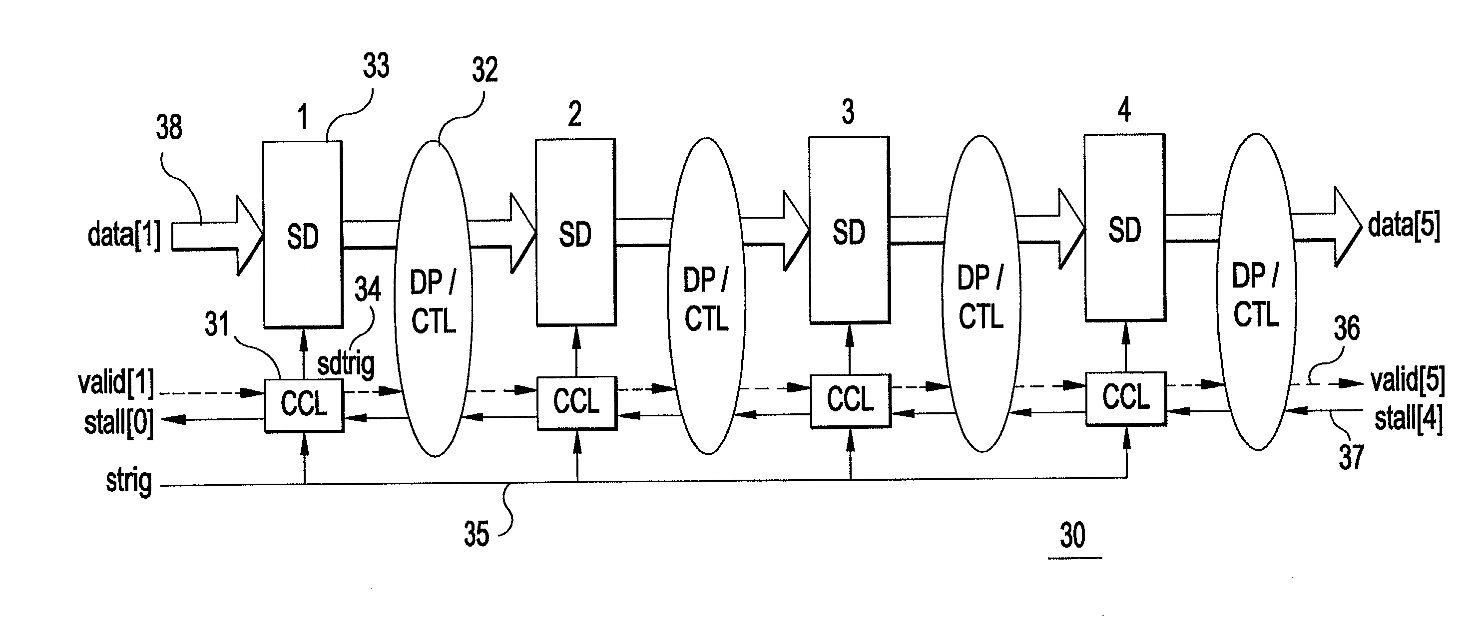
[0066]A contribution of the present invention is to achieve interlocking between stages in pipelines other than asynchronous pipelines (although the techniques apply also to asynchronous pipelines). FIGS. 2A and 2B illustrate examples of two preferred embodiments. FIG. 2A illustrates an abstract view of an interlocked pipeline 30 where the interlocking handshakes are generated in a distributed fashion by a logic circuit (CCL) 31 and through control / datapath logic (DP / CTL) 32, local to each stage. FIG. 2B illustrates an abstract view of an interlocked pipeline where the interlocking handshakes are generated in a centralized fashion by a common logic circuit 39, such as a state machine. Although not illustrated in FIG. 2B, the common logic circuit 39 may of course be an abstraction of distributed control logic, and may of course receive control and data signals from each pipeline stage and the environment of the pipeline. The register stages (SD) 33 of each stage are triggered by loca...


PUM


Abstract

An integrated circuit including a pipeline and a method of operating the pipeline. Each stage of the pipeline is triggered by one or more triggering events and are individually, and selectively, stalled by a stall signal. For each stage a stall signal, delayed with respect to the stall signal of a downstream stage, is generated and used to select whether the pipeline stage in question is triggered. A data valid signal propagating with valid data adds further selection, such that only stages with valid data are stalled.

Description

BACKGROUND OF THE INVENTION[0001]1. Field of the Invention[0002]The present invention generally relates to integrated circuits and more particularly to controlling data propagation in a pipeline circuit.[0003]2. Description of the Related Art[0004]Semiconductor technology and chip manufacturing advances have resulted in a steady increase of on-chip clock frequencies, the number of transistors on a single chip and the die size itself accompanied by a corresponding decrease in chip supply voltage. Generally, the power consumed by a given clocked unit (e.g., latch, register, register file, functional unit and etc.) increases linearly with the frequency of switching within the unit. Thus, not withstanding the decrease of chip supply voltage, chip power consumption has increased as well. In current microprocessor designs, over 70% of the power consumed is attributable to the clock alone. Typically, over 90% of this power is consumed in local clock splitters / drivers and latches.[0005]Both...

Claims


Application Information

Patent Timeline
Patent Type & Authority Patents(United States)
IPC IPC(8): H04L5/00G06F9/30G06F1/32G06F9/38G06F9/44
CPCG06F1/3203G06F1/3237G06F1/324G06F9/3869G06F1/3275Y02B60/1228Y02B60/1217Y02B60/1221G06F9/3871Y02D10/00
Inventor JACOBSON, HANS M.KUDVA, PRABHAKAR N.BOSE, PRADIPCOOK, PETER W.SCHUSTER, STANLEY E.
Owner INT BUSINESS MASCH CORP
Why Eureka
Try Eureka