
Variable cut-off offset press system and method of operation

a technology of offset press and variable cut-off plate, which is applied in the field of variable cut-off plate offset press system and method of operation, can solve the problems of inability to print the job, waste of a large portion of substrate, and high cost of strategy

Inactive Publication Date: 2006-06-27
DAY INT
View PDF15 Cites 38 Cited by
  • Summary
  • Abstract
  • Description
  • Claims
  • Application Information

AI Technical Summary

Benefits of technology

[0018]To aid in smooth operation of the system, the woven fabric ply is rigid in a direction across the width of the belt and flexible along the longitudinal axis of the belt. The base ply also preferably comprises an inner surface which is capable of providing precise registration, such as, for example, where the inner surface comprises a high friction material.

Problems solved by technology

However, should a customer require a printed image falling outside of this parameter either the press operator would not be able to print such an image with the existing press, or the print job would result in a sizable portion of substrate being wasted.
For example, if the blanket circumference is less than the length of the image to be printed, the press is incapable of printing the job.
Such a strategy is quite expensive.
The disadvantage of this type of press is that the cost of a cassette is approximately half that of a new printing unit and requires a considerable amount of downtime in order to change the cassette and perform the necessary adjustments to adapt to a new print job.
Such a gap caused vibration and other problems associated with high-speed printing.
However, because the print and blanket sleeve diameters may be mismatched, the press requires either a very high ink transfer ratio between the blanket and the substrate, or blanket cleaning after each rotation to avoid residual ink on the blanket from transferring onto the substrate.
However, problems remain in the art, particularly in obtaining precise image registration with four-color printing presses.
One problem continues to be that the dimensions of the substrate change from print station to print station as the water-based inks at each print station wet the paper substrate which is driven under tension.
Other problems include the need to clean the blanket surface to remove residual ink in some systems.

Method used


Image

  • Variable cut-off offset press system and method of operation
  • Variable cut-off offset press system and method of operation
  • Variable cut-off offset press system and method of operation

Examples


Embodiment Construction

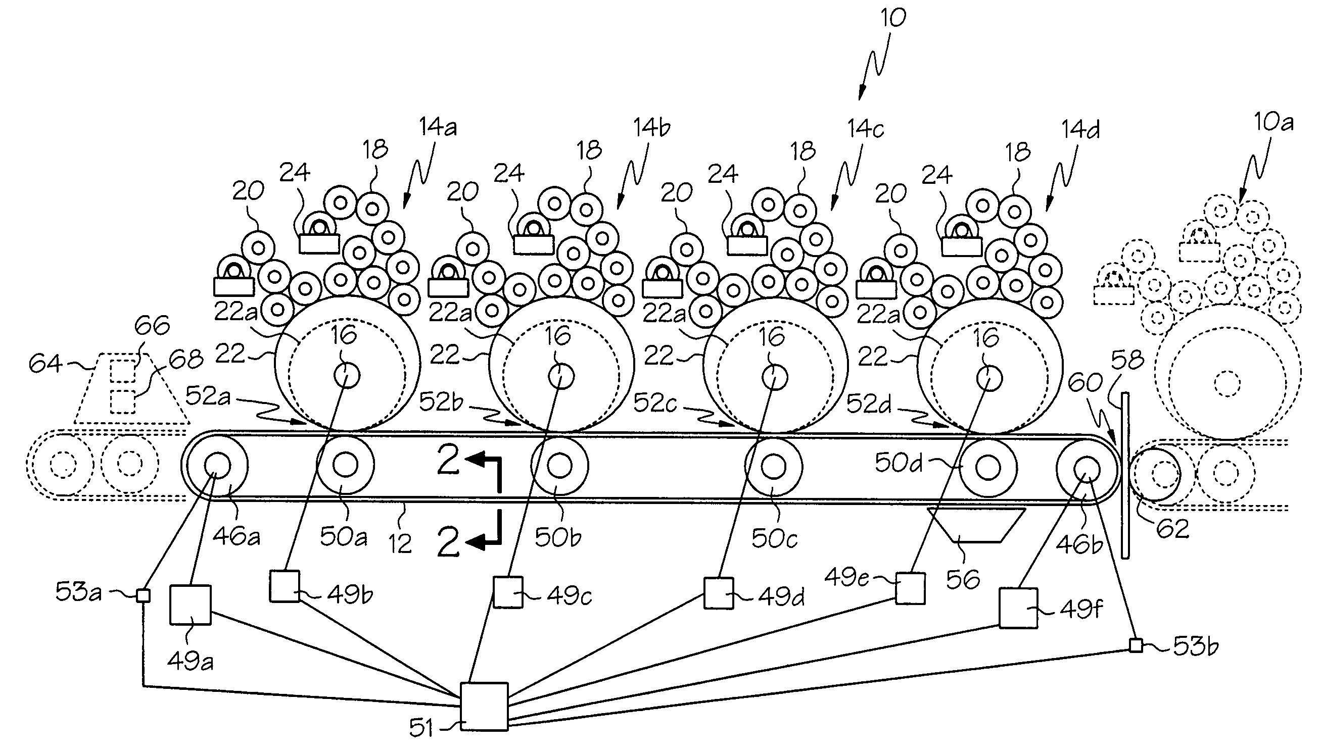
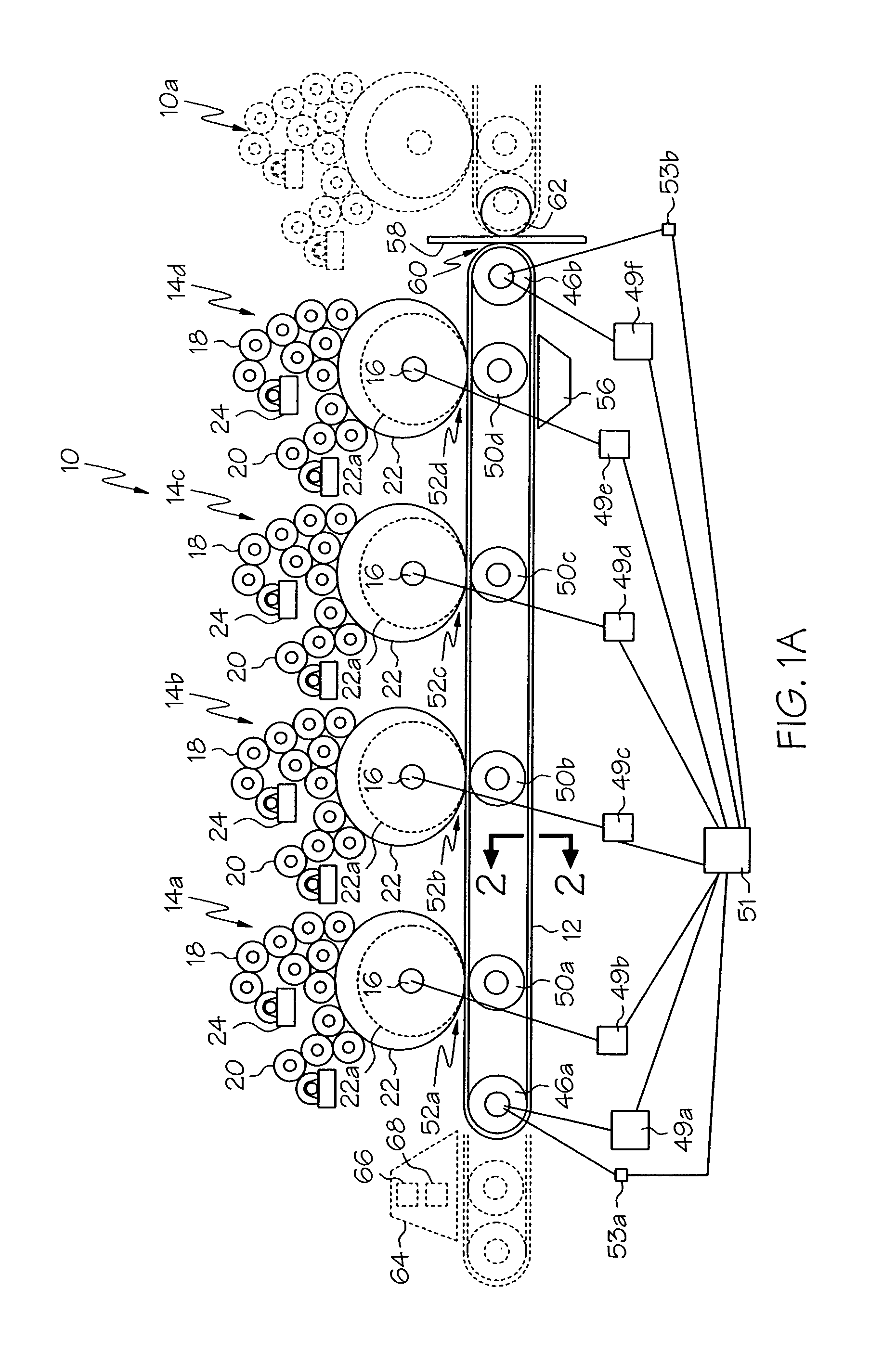
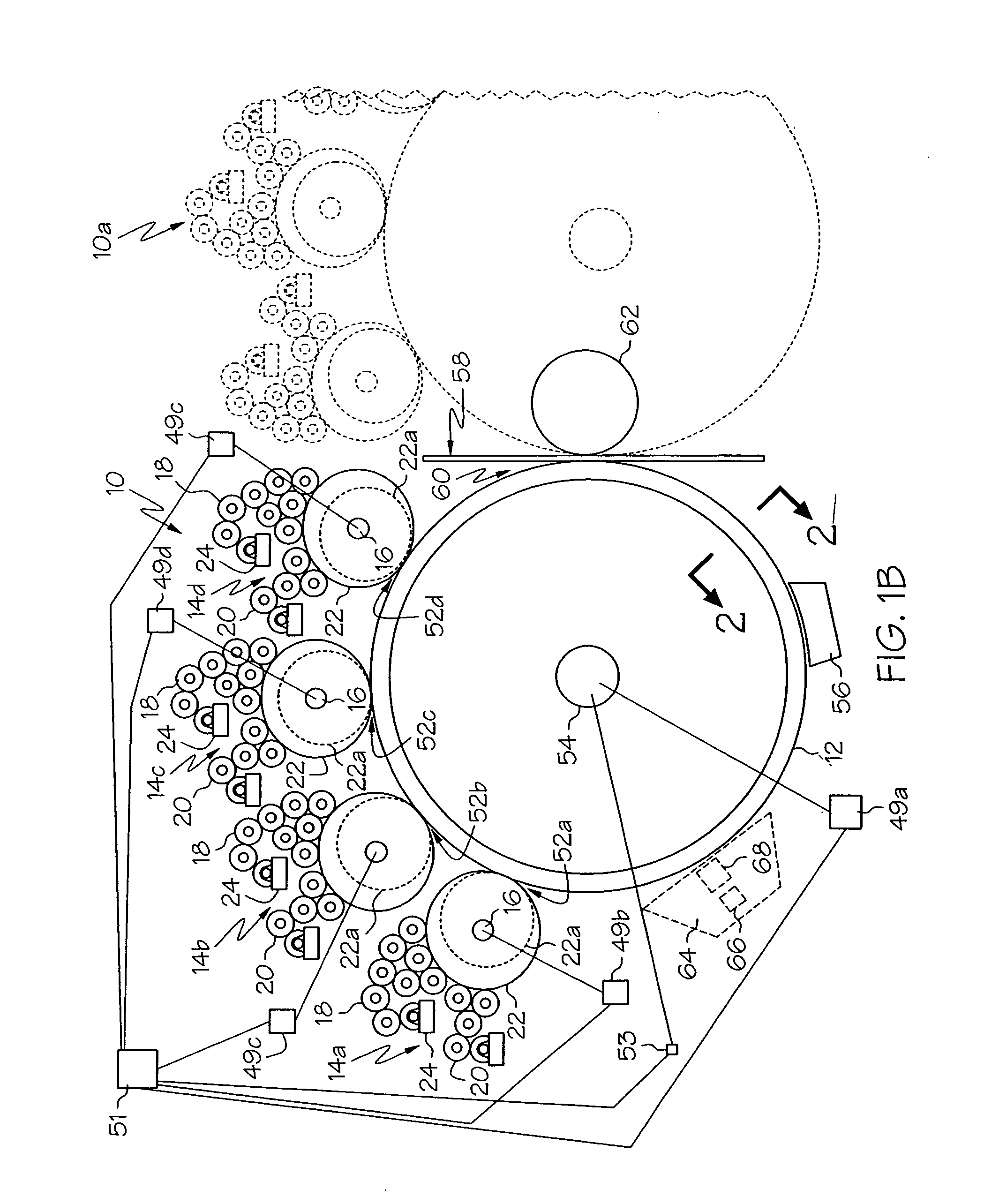
[0033]FIGS. 1A and 1B illustrate generally two embodiments of a variable cut-off offset pressing apparatus 10 and method of operation which utilize a continuous image transfer belt 12 in accordance with the present invention. In both embodiments, the apparatus 10 is intended primarily for printing on paper stock, but may be used for printing on other types of stock material. It is to be appreciated that since both embodiments shown in FIGS. 1A and 1B are essentially the same, like components are indicated with the same numeral.

[0034]Generally, to both embodiments, the apparatus 10 includes a series of image transfer stations 14a, 14b, 14c, and 14d arranged in a generally linear or arcuate configuration. However, it should be readily understood by one of ordinary skill in the art, that the image transfer stations 14a–d do not necessarily need to be arranged in a uniform linear or arcuate configuration as shown.

[0035]Each of the image transfer stations 14a–d is provided with a plate c...


PUM


Abstract

A variable cut-off offset press system and method of operation which utilizes a continuous image transfer belt is provided. The offset printing system comprises at least two plate cylinders adapted to have thereon respective printing sleeves. Each of the printing sleeves is adapted to receive colored ink from a respective ink source. An optional coating source may be provided to fully or partially coat the image transfer belt before inking. The system further comprises at least a impression cylinder, wherein the image transfer belt is positioned to contact each of the printing sleeves at respective nips formed between respective ones of the plate cylinders and the at least one impression cylinder. An image belt cleaning station adapted to remove residual ink or coating from the surface of the image transfer belt after image transfer of a multicolored image from the image transfer belt to a substrate is also provided.

Description

BACKGROUND OF THE INVENTION[0001]This invention relates to a variable cut-off offset press system and method of operation, and more particularly to such a system which utilizes a continuous image transfer belt.[0002]Commercial printers have used a variety of different printing techniques such as gravure printing, flexographic printing, and offset printing. Each of these techniques basically involves the step of inking a plate containing an image to be printed and transferring the ink (which now represents an image) onto a substrate such as, for example, paper, cardboard, film, and foil.[0003]A typical single color offset printing press includes a plate cylinder, a blanket cylinder, and an impression cylinder, each rotationally mounted on the press. Four-color presses require individual print stations with plate, blanket, and impression cylinders for each color. The plate cylinder carries a printing plate having a surface defining an image to be printed. The blanket cylinder carries ...

Claims


Application Information

Patent Timeline
IPC IPC(8): B41F5/16B41F7/02B41F7/08B41F13/44B41F17/00
CPCB41F7/08B41F17/007B41F13/44
Inventor MCLEAN, MICHAEL EDWARDERBSTEIN, ROBERT STEPHENRESLOW, LIEF FREDERICK
Owner DAY INT
Learn More