
Method and apparatus for treating a subterranean formation
a subterranean formation and subsurface technology, applied in the direction of fluid removal, wellbore/well accessories, sealing/packing, etc., can solve the problems of excessive seal wear, tool position error, and unbalanced hydraulic area of the sleeve valve, so as to achieve less seal wear, eliminate tool movement, and simple upward and downward cycling
- Summary
- Abstract
- Description
- Claims
- Application Information
AI Technical Summary
Benefits of technology
Problems solved by technology
Method used
Image

Examples
Embodiment Construction
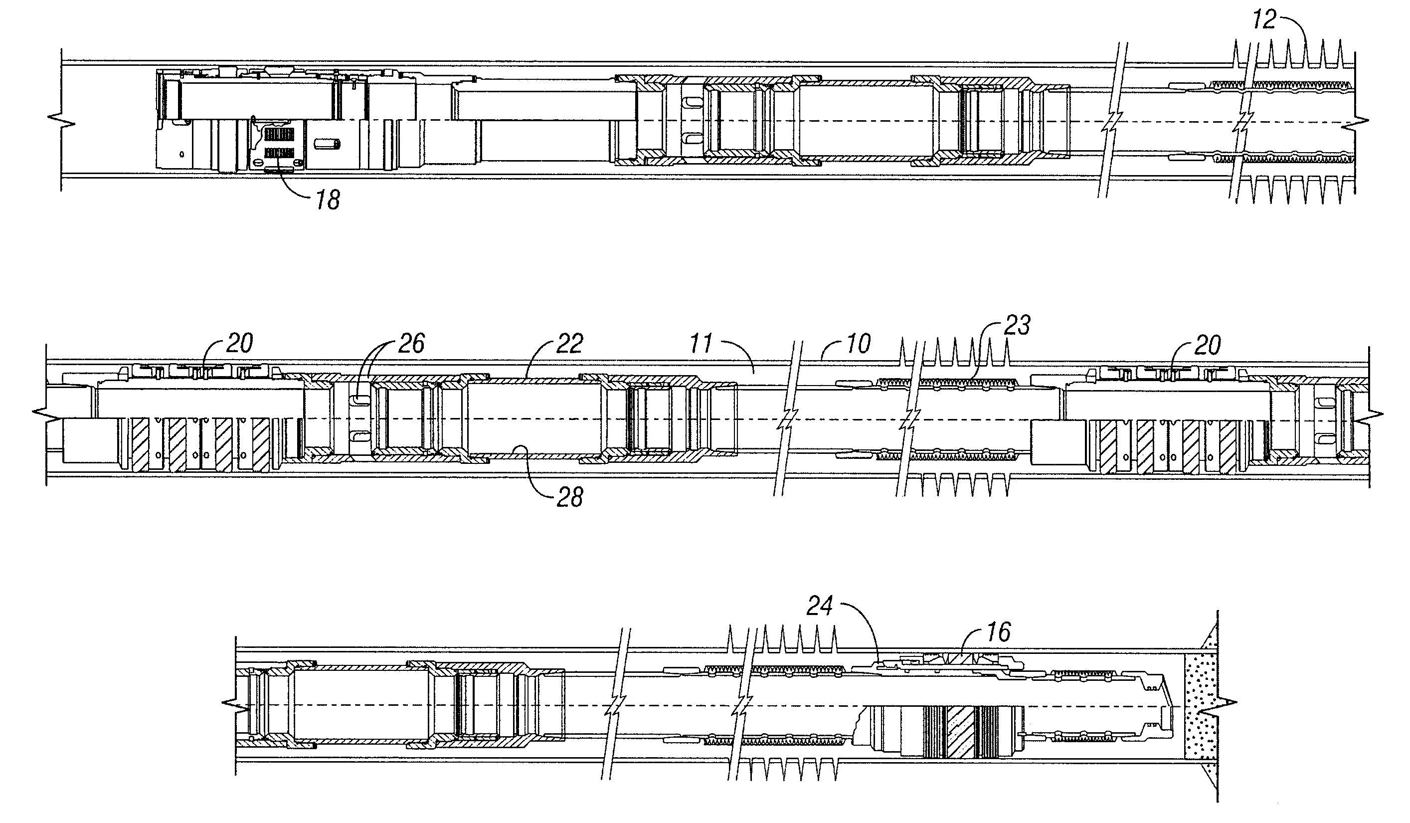
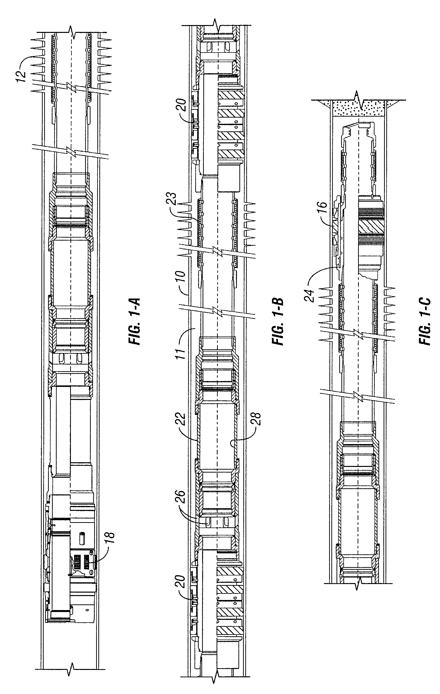
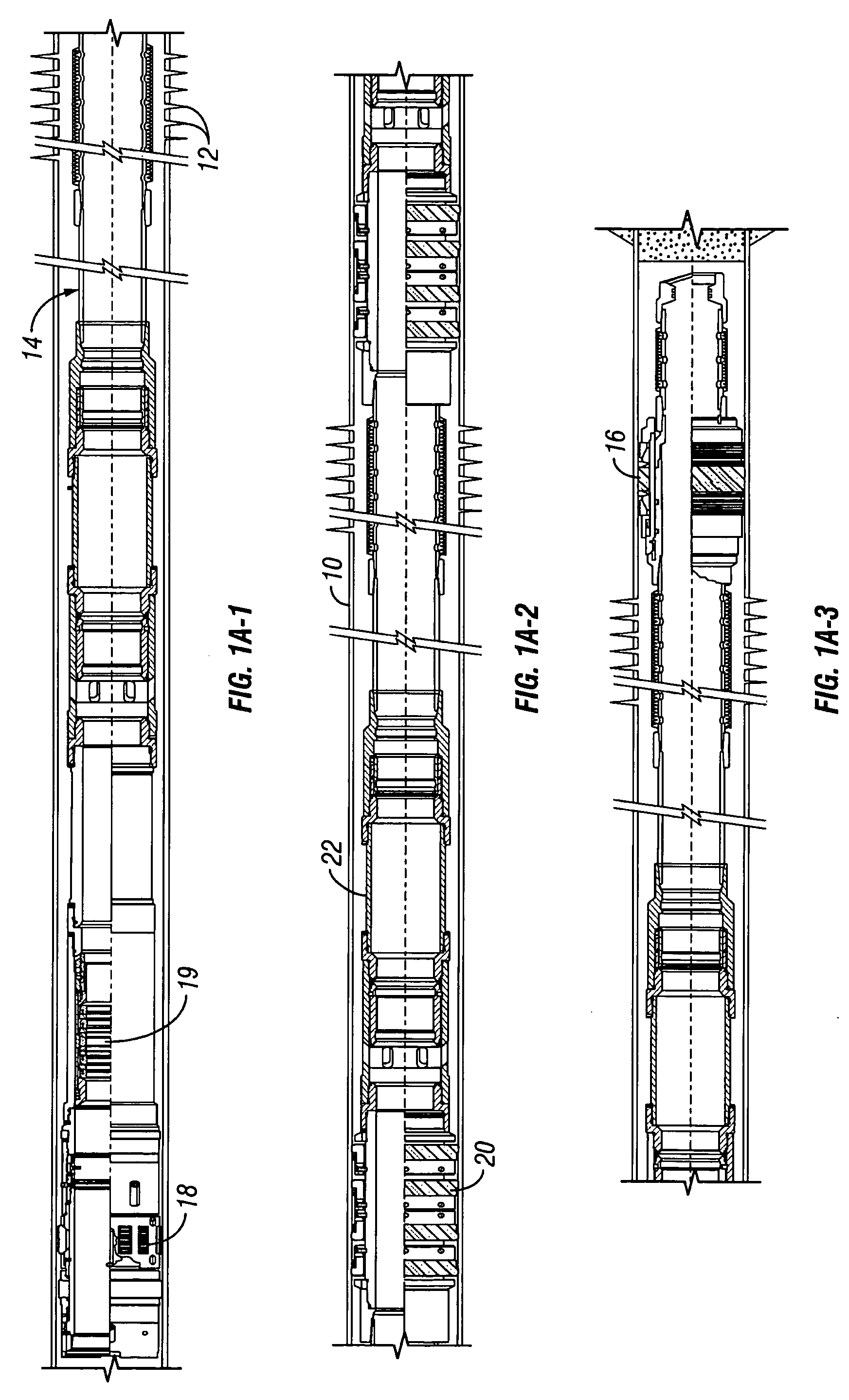
[0053]Referring now to the drawings and first to FIG. 1, a well casing is shown generally at 10 and is perforated at a plurality of intervals as shown at 12 for completion of the well for production of petroleum products from a plurality of subsurface zones. Though the well perforations are shown to be substantially evenly spaced, it is to be understood that the casing perforations are typically located in unevenly spaced relation, the spacing thereof being determined by the location or depth and width of different subsurface zones of interest.
[0054]A service service / completion liner shown generally at 14, which is designed for use with a service tool having a hydraulically actuated dump valve, is shown to be located within the perforated well casing 10 and is adapted to latch into a sump packer 16 that establishes sealing within the well casing. The sump packer and isolates the multiple perforated zones of the well casing from pressure conditions below the lowermost perforated zone...
PUM
 Abstract
Description
Claims
Application Information