
Light pipe, color illumination system adopting the light pipe, and projection system employing the color illumination system

Inactive Publication Date: 2006-06-27
SAMSUNG ELECTRONICS CO LTD
View PDF19 Cites 1 Cited by
  • Summary
  • Abstract
  • Description
  • Claims
  • Application Information

AI Technical Summary

Benefits of technology

[0014]Another aspect of the present invention provides a color illumination system which has a simple optical configuration and can illuminate a display device with color beams that are scrolled.
[0015]Still another aspect of the present invention provides a single-panel projection system designed so that scrolling is easily synchronized with the operation of the display device, while having a simple optical configuration.
[0016]The present invention provides a light pipe which can provide various color gamuts or various color temperatures by differentiating the areas of color bars according to color, and a projection system adopting the light pipe.
[0017]The present invention also provides a projection system which is made compact by including a single color scrolling unit and effectively performs color scrolling to improve the quality of an image.

Problems solved by technology

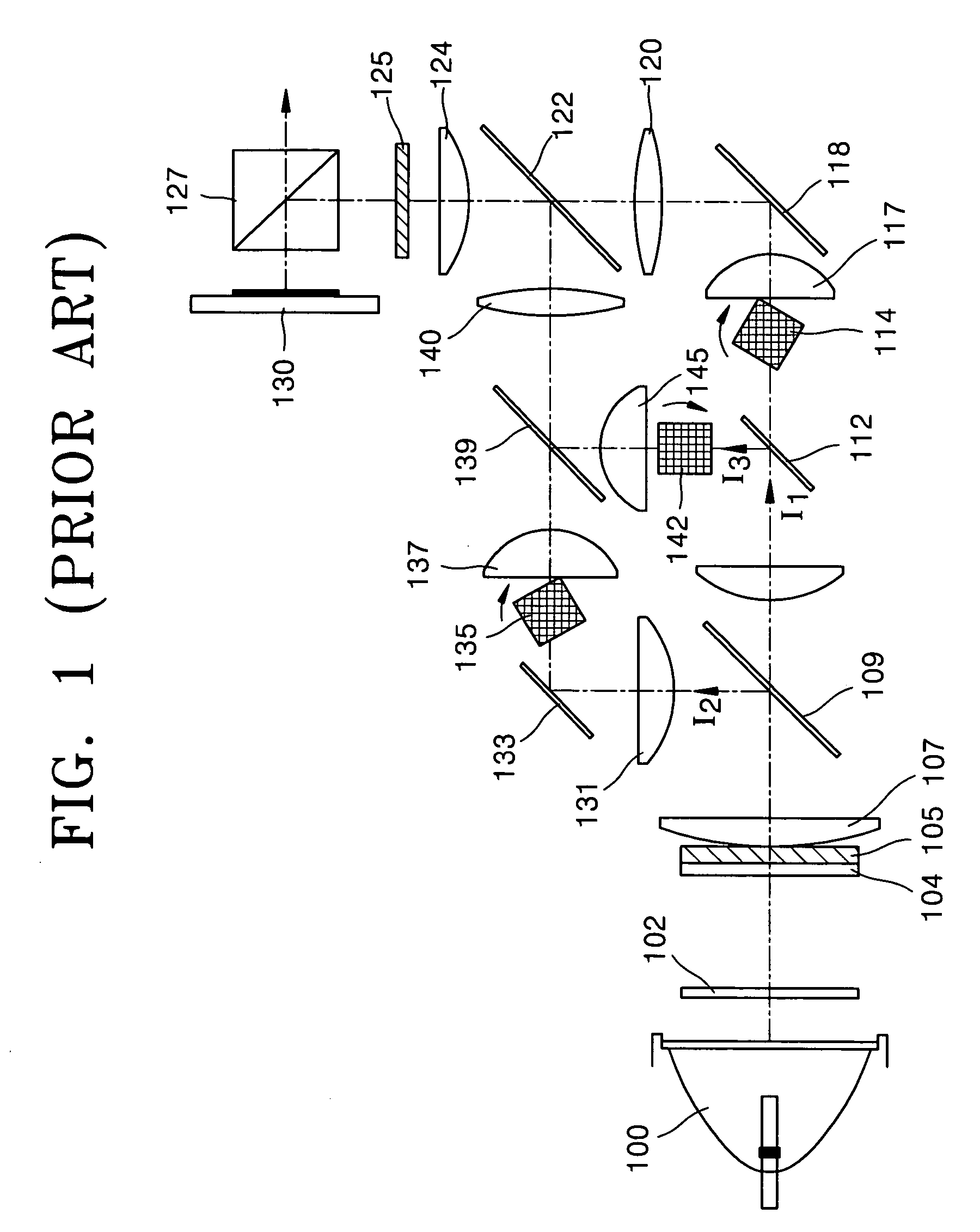
Accordingly, an optical system is large, and yield is degraded due to a complicate manufacturing and assembling process.
In addition, a large amount of noise is generated due to the driving of three motors for rotating the first through third prisms 114, 135, and 142, and the manufacturing costs of a conventional projection system adopting the above-described method is increased compared to a color wheel method adopting only one motor.
However, controlling the synchronization is not easy.
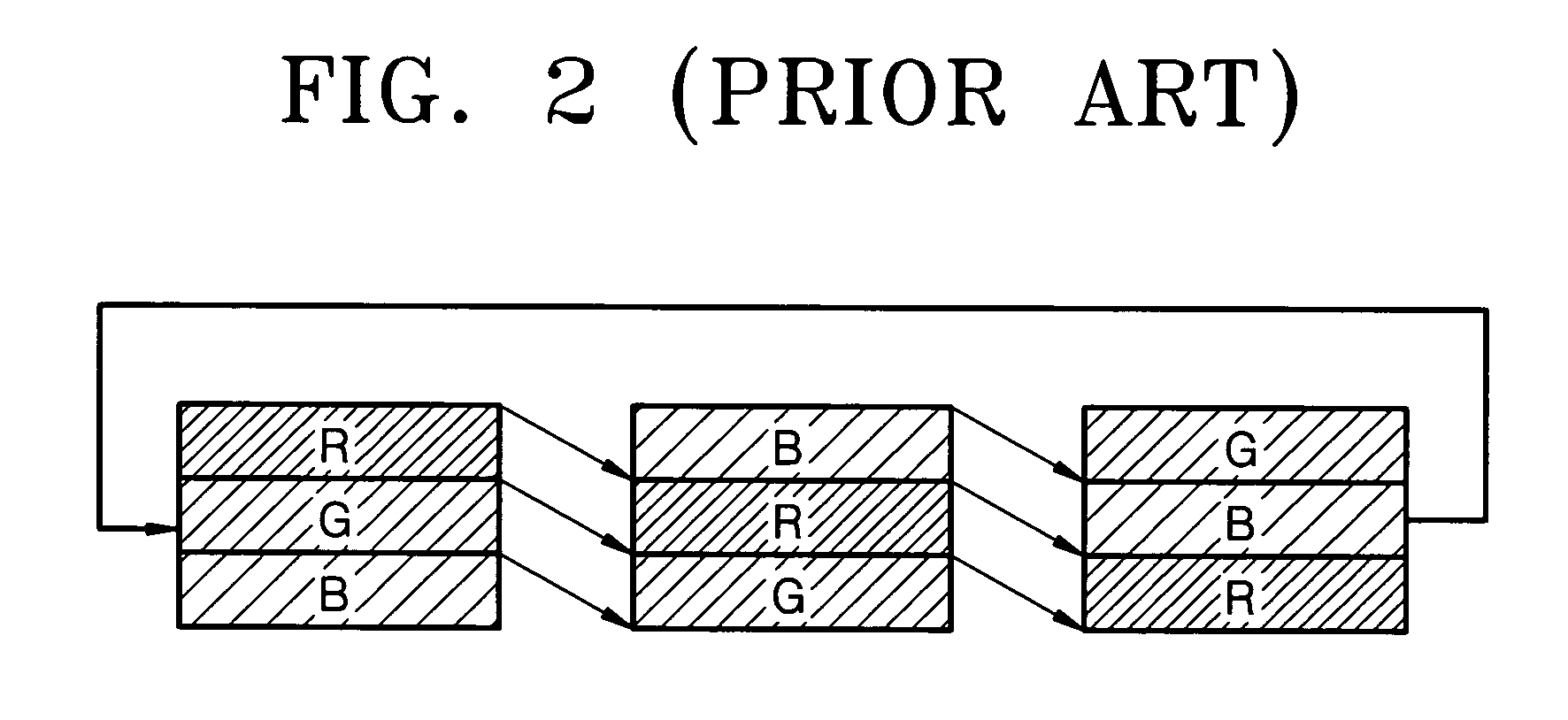
Further, because the scrolling prisms 114, 135, and 142 make circular motions, the speed of color scrolling by the three scrolling prisms is irregular, consequently deteriorating the quality of an image.

Method used


Image

  • Light pipe, color illumination system adopting the light pipe, and projection system employing the color illumination system
  • Light pipe, color illumination system adopting the light pipe, and projection system employing the color illumination system
  • Light pipe, color illumination system adopting the light pipe, and projection system employing the color illumination system

Examples


first embodiment

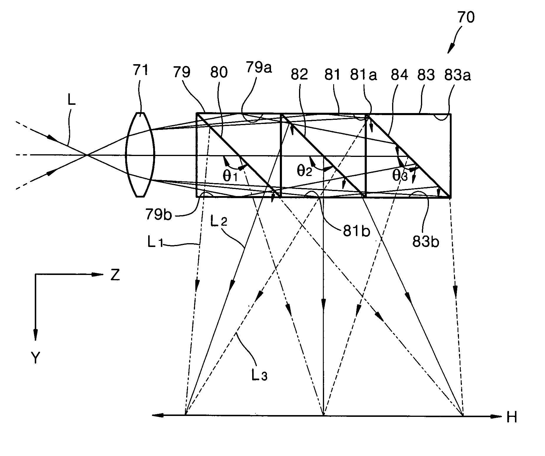
[0060]To achieve this, the light pipe 70 according to the present invention includes a plurality of dichroic prisms, each of which reflects light in a particular wavelength range and at the same time transmits light in other wavelength ranges so that incident light (L) can be separated according to a wavelength range. As shown in FIG. 4, the light pipe 70 includes first, second, and third dichroic prisms 79, 81, and 83 for separating the incident light L into first, second, and third color beams L1, L2, and L3.

[0061]The first dichroic prism 79 has a first mirror plane 80, which is inclined by an angle θ1 with respect to the optical axis of the incident light L. The first mirror plane 80 reflects the first color beam L1 among the incident light L and transmits the second and third color beams L2 and L3. In other words, the first mirror plane 80 reflects a blue beam B and transmits beams of other colors.

[0062]The first dichroic prism 79 also has first reflective planes 79a and 79b, wh...

second embodiment

[0116]As shown in FIG. 17, the light pipe 315 according to the present invention includes first, second, and third dichroic prisms 318, 319, and 320. The first dichroic prism 318 has a first dichroic mirror plane 318a for reflecting an incident beam of a particular color and transmitting incident beams of the other colors. The second dichroic prism 319 is installed on the path of light transmitted by the first dichroic prism 318 and has a second dichroic mirror plane 319a for reflecting an incident beam of a particular color and transmitting incident beams of the other colors. The third dichroic prism 320 is installed on the path of light transmitted by the second dichroic mirror plane 319a and has a third dichroic mirror plane 320a for reflecting an incident beam of a particular color and transmitting incident beams of the other colors. When the sizes of the first, second, and third dichroic mirror planes 318a, 319a, and 320a are S1, S2, and S3, respectively, at least two of the si...

third embodiment

[0157]A color illumination system of the projection system according to the present invention includes the light source 410, the light pipe 415 for separating light emitted from the light source 410, according to color, and the scrolling unit 430 for scrolling R, G, and B beams, into which the light emitted from the light source 410 has been separated by the light pipe 415, so as to continuously change the paths of the R, G, and B beams. The color illumination system may further include the first and second cylindrical lenses 425 and 431 and the first and second fly-eye lens arrays 433 and 435 so as to achieve highly-efficient scrolling of the light emitted from the light source 410. The first and second cylindrical lenses 425 and 431 are respectively installed in front of and behind the scrolling unit 430, and the first and second fly-eye lens arrays 433 and 435 enable the R, G, and B beams transmitted by the scrolling unit 430 to land on three respective color areas of the light v...


PUM


Abstract

A light pipe for separating incident light according to color, a color illumination system adopting the light pipe, and a projection system adopting the color illumination system are provided. Since the projection system is a single-panel projection system adopting a scrolling unit, its optical configuration is simplified. Also, the light pipe of the projection system is comprised of different-sized color separation units, thus improving the color gamut and the color temperature. Further, the light pipe includes color selection polarizers, each of which changes the polarization direction of a color beam with a specific wavelength, thereby improving light efficiency.

Description

BACKGROUND OF THE INVENTION[0001]This application claims the benefits of Korean Patent Applications Nos. 2002-82093, 2003-4840, 2003-12699, and 2003-16843, filed on Dec. 21, 2002, on Jan. 24, 2003, on Feb. 28, 2003, and on Mar. 18, 2003, respectively, in the Korean Intellectual Property Office, the disclosures of which are incorporated herein in their entireties by reference.[0002]1. Field of the Invention[0003]The present invention relates to a light pipe which increases light efficiency and has a small size by separating incident light according to color without light loss and scrolling the separated color beams, a color illumination system adopting the light pipe, and a projection system adopting the color illumination system.[0004]2. Description of the Related Art[0005]Projection systems are classified into 3-panel projection systems and single-panel projection systems according to the number of light valves that form an image by controlling the on / off operation of light emitted...

Claims


Application Information

Patent Timeline
IPC IPC(8): G03B21/28G02F1/1335G02B27/00G02B27/14H04N9/31
CPCG02B27/1033G02B27/1053H04N9/3197G02B27/145H04N9/3117G02B27/123G02B26/0875G02B27/286
Inventor KIM, SUNG-HACHO, KUN-HOKIM, DAE-SIKLEE, HEE-JOONG
Owner SAMSUNG ELECTRONICS CO LTD
Learn More