Micromixer

a micro-mixer and mixing machine technology, applied in the field of micro-mixers, can solve the problems of high production cost, complex machining method, and inconvenient production of fluids, and achieve the effects of simple structure, high mixing performance, and easy production

Inactive Publication Date: 2006-06-27
YAMATAKE HONEYWELL CO LTD
View PDF24 Cites 16 Cited by
  • Summary
  • Abstract
  • Description
  • Claims
  • Application Information

AI Technical Summary

Benefits of technology

[0006]An object of the invention is to provide a micro-mixer which does not become clogged wit...

Problems solved by technology

However, in conventional micro-mixers, passages for combining and dividing fluids (liquids) are minute and require high production accuracy.
Hence, the method of machining (producing) them is complicated.
Further, accurate alignment is required, which leads to high production cost.
Further, since the passa...

Method used


Image

  • Micromixer
  • Micromixer
  • Micromixer

Examples


Embodiment Construction

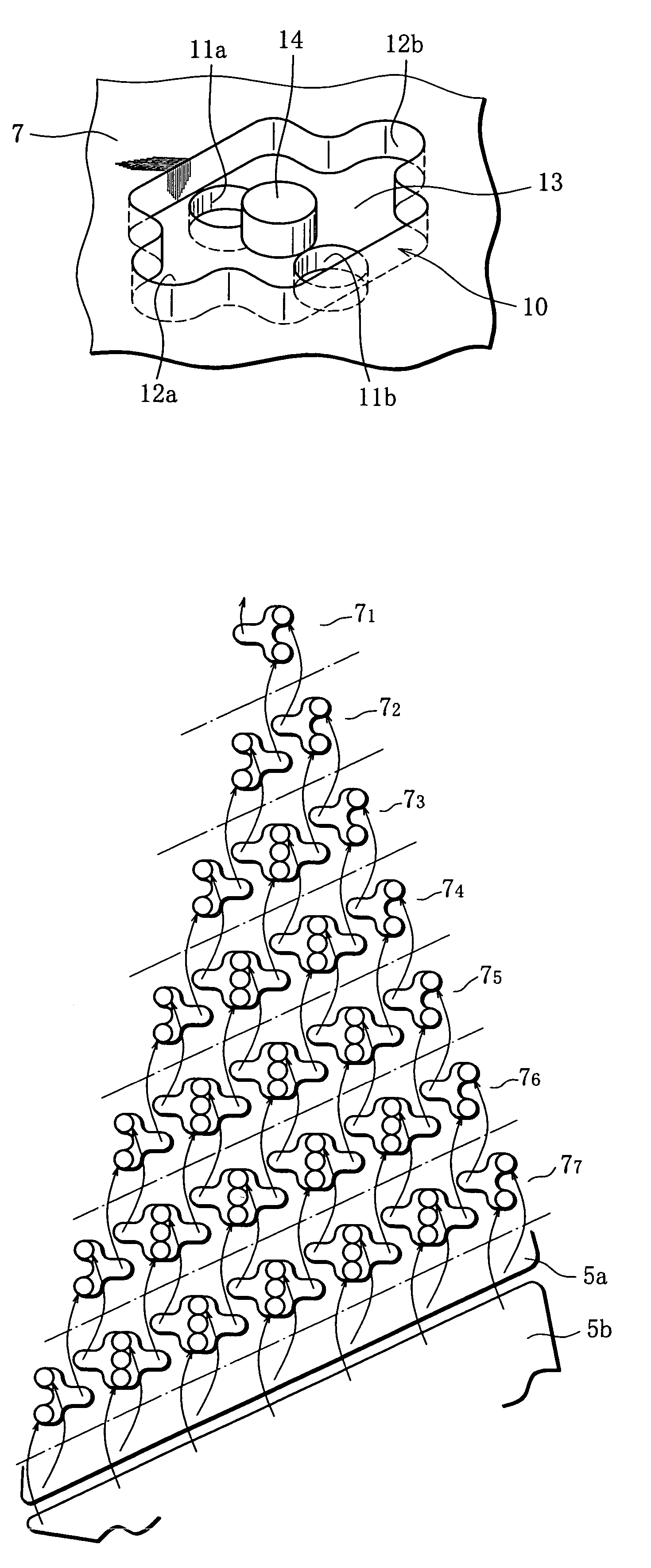
[0027]Referring to the drawings, an embodiment of the invention will be described, using an example of a micro-mixer for mixing two kinds of liquids A and B, expediting their diffusion.

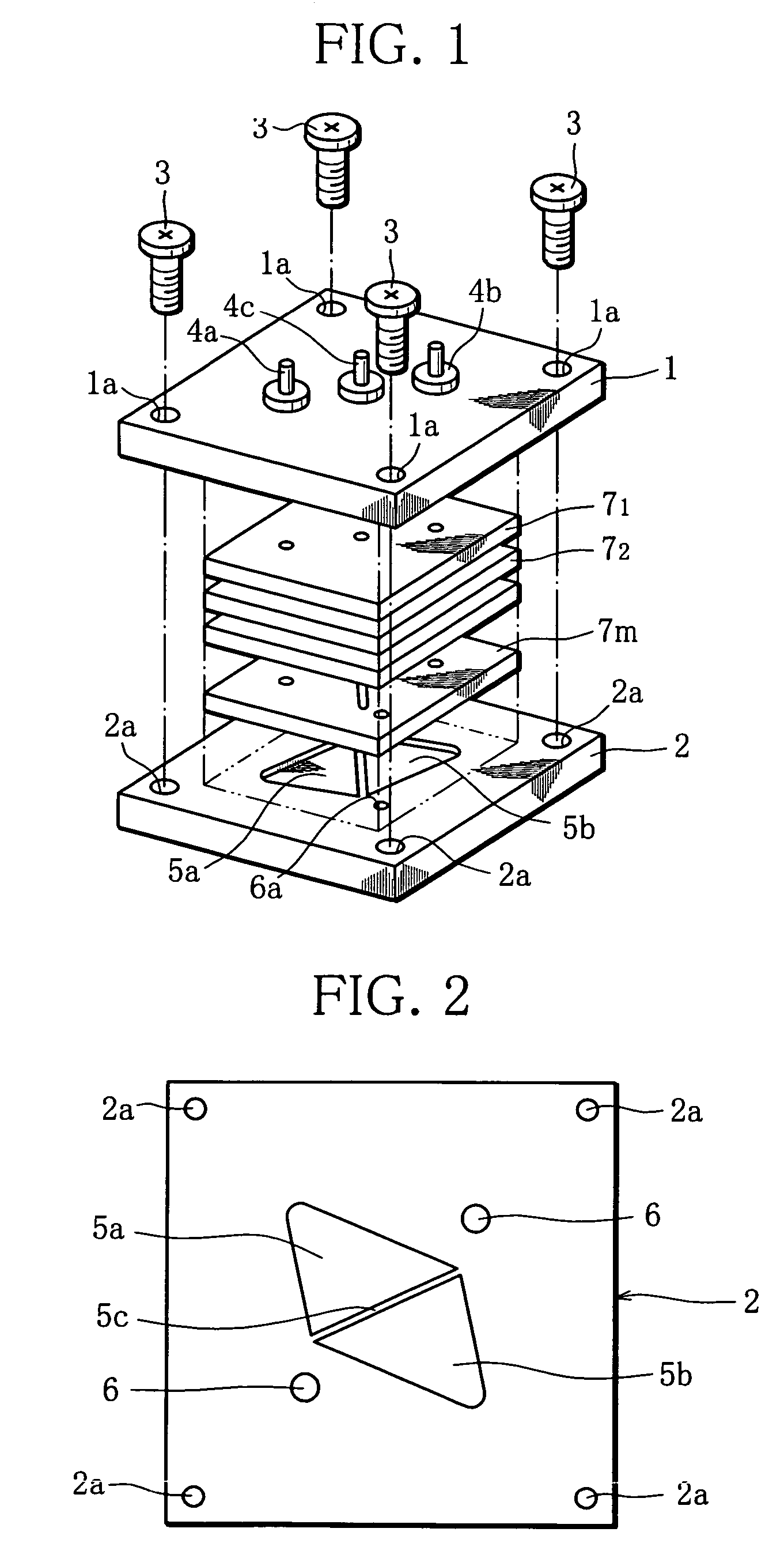
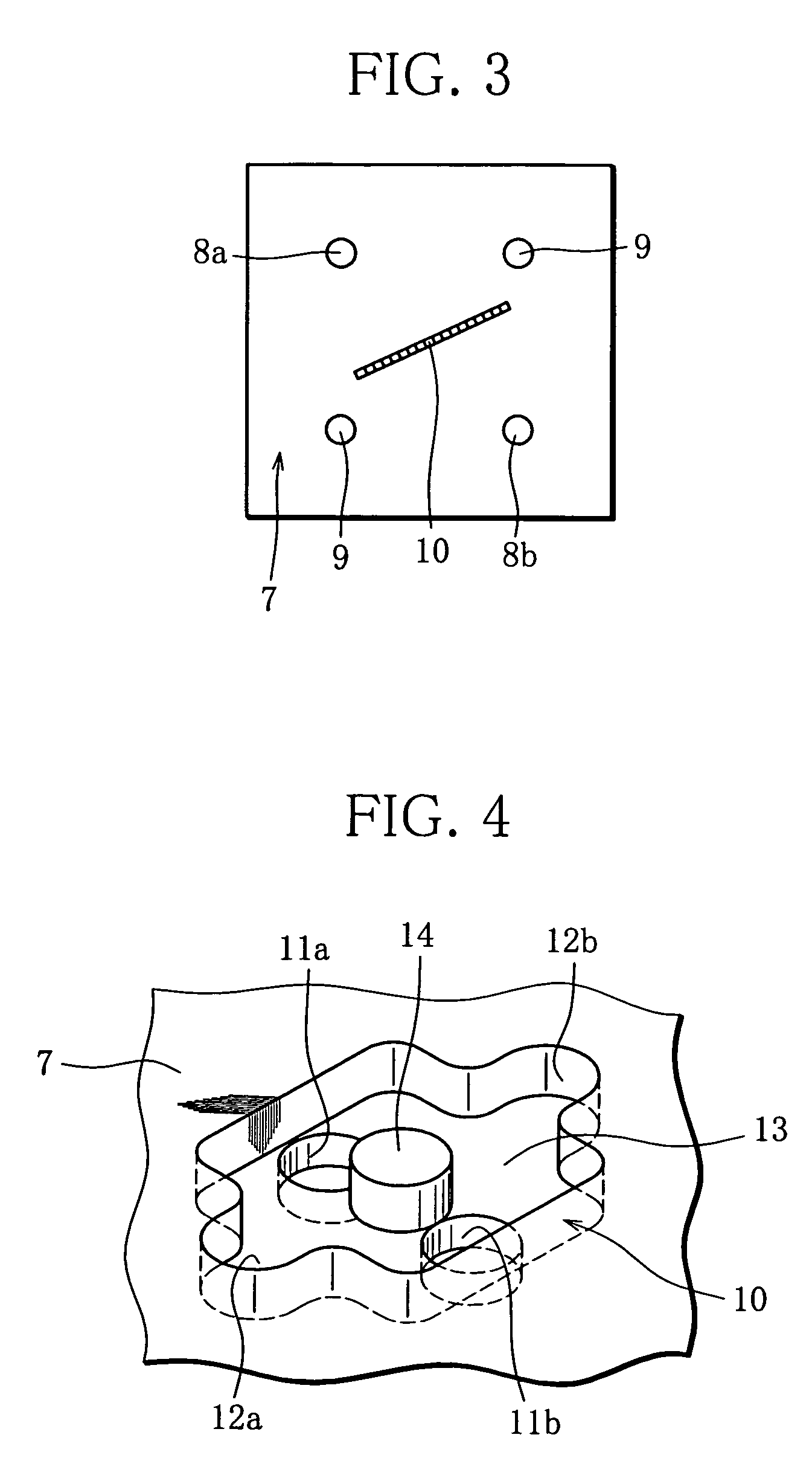
[0028]FIG. 1 is an exploded perspective view showing a schematic structure of a micro-mixer according to this embodiment, where reference numerals 1 and 2 denote upper and lower plates, respectively. The upper and lower plates 1, 2 are flat square-like plates of, for example, 5 mm in thickness and about 50 mm in length of one side, made of Al material, SUS or the like. The plate 1 has through-holes 1a at its four corners, while the plate 2 has screw holes 2a at its four corners. The plates 1 and 2 are combined together with a plurality of passage modules (described later) between them, by fastening four bolts 3 through the through-holes 1a in the upper plate 1 into the screw holes 2a in the lower plate 2.

[0029]The upper plate 1 has three through-holes (not shown) in its central part, which are arrange...


PUM

PropertyMeasurementUnit
Lengthaaaaaaaaaa
Diameteraaaaaaaaaa
Widthaaaaaaaaaa

Abstract

A micro-mixer of a simple structure suited to form a micro-mixed liquid from two kinds of liquids A and B comprises a plurality of passage modules 7 stacked and thereby forming a multi-tiered flow passage. Each of the passage modules has a plurality of combining-dividing units 10 arranged at regular intervals. Each of the combining-dividing units has two inlets 11a, 11b and two outlets 12a, 12b. The two outlets 12a, 12b of each of the combining-dividing units in each of the stacked passage modules are connected with an inlet 11a of a combining-dividing unit and an inlet 11b of another combining-dividing unit in its immediate downstream passage module, respectively.

Description

[0001]This application is a U.S. National Phase Application under 35 USC 371 of International Application PCT / JP02 / 05064 filed May 24, 2002.TECHNICAL FIELD[0002]The invention relates to a micro-mixer which exhibits high mixing performance, is easy to produce, and has a simple structure.BACKGROUND ART[0003]A micro-mixer is produced, for example, by machining a semiconductor substrate of Si or the like employing a micro-machining technique.[0004]In a micro-mixer of this type, for example, two kinds of liquids (fluids) A, B are combined to form a two-layer laminar flow (A+B), and then the laminar flow (A+B) is divided into two half-flows (A+B) / 2 along the direction of the laminar flow. Then, two half-flows (A / 2+B / 2) are combined to form a four-layer laminar flow (A / 2+B / 2+A / 2+B / 2), and then this laminar flow is divided in two along the direction of the laminar flow. By repeating combining of laminar flows and dividing of a laminar flow along its direction this way, the liquids A, B are ...

Claims


Application Information

Patent Timeline
IPC IPC(8): B81B1/00B01F5/00B01F3/08B01F5/06B01F13/00
CPCB01F5/0604B01F5/064B01F15/00935B01F15/0264B01F13/0059B01F3/08Y10S366/03B01F2215/0431B01F23/40B01F25/422B01F25/432B01F33/30B01F35/561B01F35/7182
Inventor HONDA, NOBUAKI
Owner YAMATAKE HONEYWELL CO LTD
Why Eureka
Try Eureka