Gas powered heat delivery system

a heat delivery system and gas technology, applied in the direction of lighting and heating apparatus, heating types, applications, etc., can solve the problems of electrical hazards, electrical heat generation of structures and equipment in hazardous locations, and electrical heating of exposed electrical elements, etc., to achieve reliable and economical, compact, and environmentally safe effects

Inactive Publication Date: 2006-06-27
PRISM INTEGRATED SOLUTIONS
View PDF14 Cites 6 Cited by
  • Summary
  • Abstract
  • Description
  • Claims
  • Application Information

AI Technical Summary

Benefits of technology

[0002]The present invention is directed towards a heat delivery system that may heat items of many shapes, sizes and configurations, and that is environmentally safe, compact, energy efficient, explosion proof, dependable and economical.

Problems solved by technology

Heating of structures and equipment in hazardous locations poses design problems.
Exposed electrical elements can pose an electrical hazard.
These explosion proof electrical heat tapes and cables must be carefully installed to comply with electrical codes, and require a source of electrical power, which may not be available in remote locations.

Method used


Image

  • Gas powered heat delivery system
  • Gas powered heat delivery system

Examples


Embodiment Construction

[0007]In this patent document, “comprising” means “including”. In addition, a reference to an element by the indefinite article “a” does not exclude the possibility that more than one of the elements is present. The use of the word “connected” means connected in a manner that allows operation of the components connected.

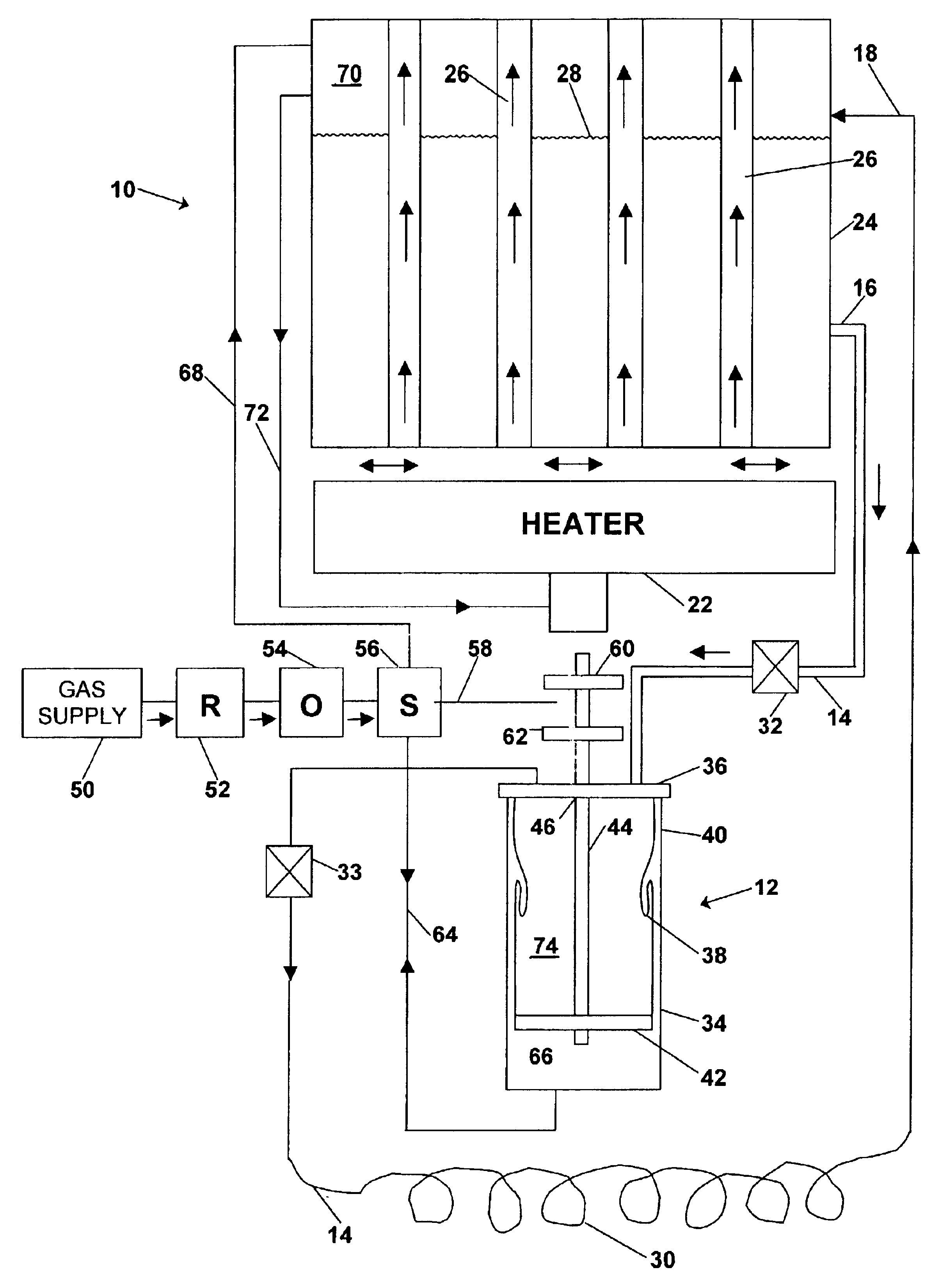
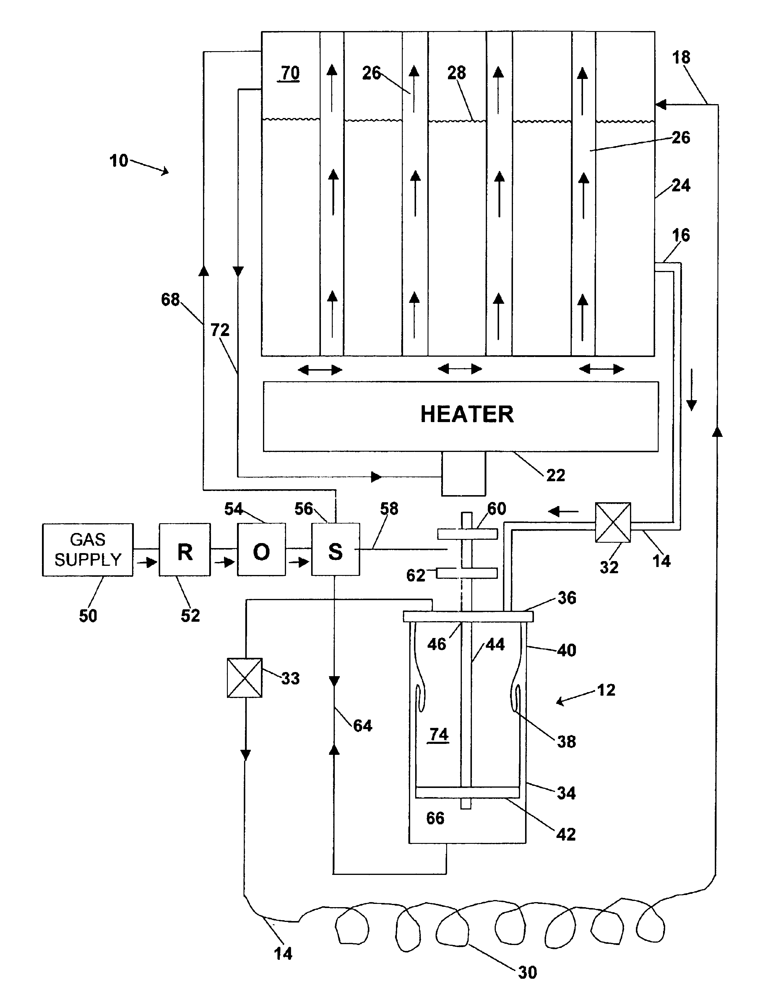
[0008]Referring to the FIGURE, the main components of a gas powered heat delivery system according to a preferred embodiment of the invention are a fluid heating section 10, a fluid pump 12 and a heat delivery conduit 14. The fluid pump 12 lies in the heat delivery conduit 14 between an inlet 16 for receiving fluid from the fluid heating section 10 and outlet 18 for delivering fluid to the fluid heating section 10. The fluid heating section 10 is preferably formed of a heater 22 and a tank 24. The heater may be a catalytic infra-red heater, as for example a CATA-DYNE™ infrared oven available from CCI Thermal Technologies Inc. of Edmonton, Alberta, Canada. Catalytic h...


PUM


Abstract

A gas powered heat delivery system, comprising a fuel gas supply, a catalytic heater connected to the fuel gas supply; a tank containing fluid, the tank being disposed to receive heat from the catalytic heater; a one way conduit having an inlet for receiving fluid from the tank, an outlet for delivering fluid to the tank, and a heat delivery section; a rolling diaphragm pump connected to the one way conduit for pumping heated fluid through the one way conduit from inlet to outlet, the rolling diaphragm pump being connected to the fuel gas supply to operate the rolling diaphragm pump; and a switch for switching the fuel gas supply between the rolling diaphragm pump and the catalytic heater, the switch being operated by the rolling diaphragm pump. Propane may be used as the fuel gas. Glycol may be used as the heating fluid. The gas powered heat delivery system may be used to heat oilfield equipment, for example at a well site, or items in other environments, particularly where vapors pose an explosion hazard.

Description

BACKGROUND OF THE INVENTION[0001]Heating of structures and equipment in hazardous locations poses design problems. In many industries, particularly in the oil industry, there are many locations that may contain explosive and flammable gases but require heating. Exposed electrical elements can pose an electrical hazard. Explosion proof electrical heat tape or cable is known that is used for heating various shapes, sizes and configurations of objects to be heated. These explosion proof electrical heat tapes and cables must be carefully installed to comply with electrical codes, and require a source of electrical power, which may not be available in remote locations.SUMMARY OF THE INVENTION[0002]The present invention is directed towards a heat delivery system that may heat items of many shapes, sizes and configurations, and that is environmentally safe, compact, energy efficient, explosion proof, dependable and economical.[0003]Therefore, according to an aspect of the invention, there ...

Claims


Application Information

Patent Timeline
Patent Type & Authority Patents(United States)
IPC IPC(8): F24H4/02F04B43/113F24D3/02F24H1/36
CPCF04B43/113F24H1/36F24D3/02
Inventor RAJEWSKI, ROBERT C.
Owner PRISM INTEGRATED SOLUTIONS
Why Eureka
Try Eureka