Pressure regulation of a fuel cell hydrogen tank system

a fuel cell hydrogen tank and pressure regulation technology, applied in the field of delivery systems, can solve the problems of substantial simplification of the system, increase in system complexity, and complex fuel cell systems, and achieve the effect of high quality control

Active Publication Date: 2006-06-27
GM GLOBAL TECH OPERATIONS LLC
View PDF13 Cites 4 Cited by
  • Summary
  • Abstract
  • Description
  • Claims
  • Application Information

AI Technical Summary

Benefits of technology

[0009]The principal object of the present invention is to design a delivery system of the initially named kind and a fuel cell system and a method of delivering a gaseous fuel so that the demands made on the control valve are smaller, whereby favorably priced control valves can be used and a high quality control of the delivered fuel mass flow can nevertheless be achieved.
[0013]Through the measure taken in accordance with the invention the pressure at the outlet of the mechanical pressure regulating valve is changed in accordance with the pressure changes downstream of the control valve in the same sense, whereby the pressure difference between the inlet side of the control valve and the outlet side of the control valve becomes smaller. In this way, the demands placed on the control valve, which is disposed between the mechanical regulating valve and the consumer or the fuel cell stack and which sets the required quantity of the gaseous fuel in dependence on the load, are reduced.

Problems solved by technology

The choice of the fuel has in this respect a substantial influence on the complexity of the fuel cell system.
When using organic fuels such as for example methanol or gasoline, the system complexity increases because of the required reformation of fuel to form hydrogen-rich gas.
The use of pure hydrogen results in a substantial simplification of the system.
This leads to relatively high demands being placed on the quality of the control valve and its ability to respond.

Method used


Image

  • Pressure regulation of a fuel cell hydrogen tank system
  • Pressure regulation of a fuel cell hydrogen tank system

Examples


Embodiment Construction

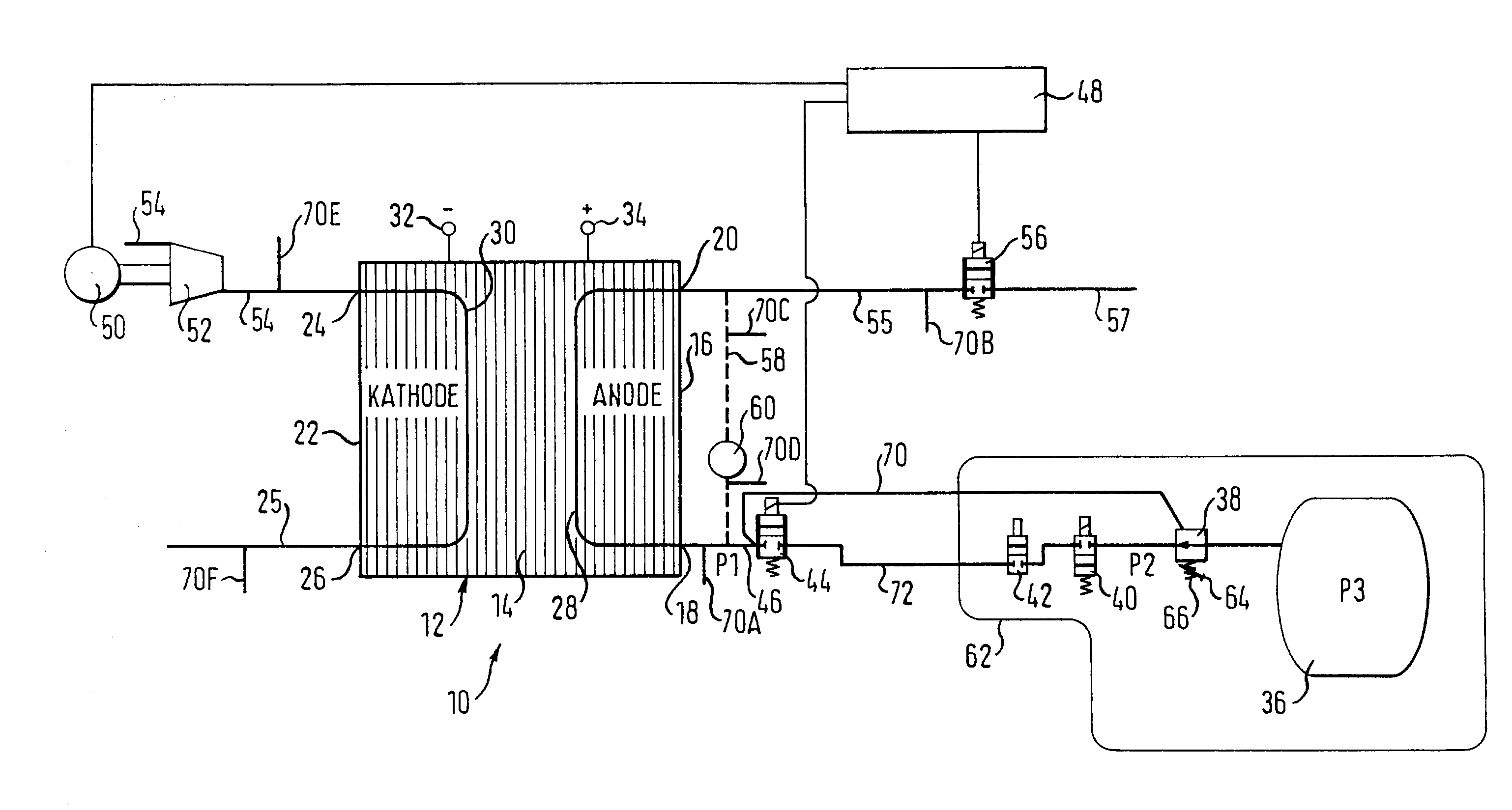
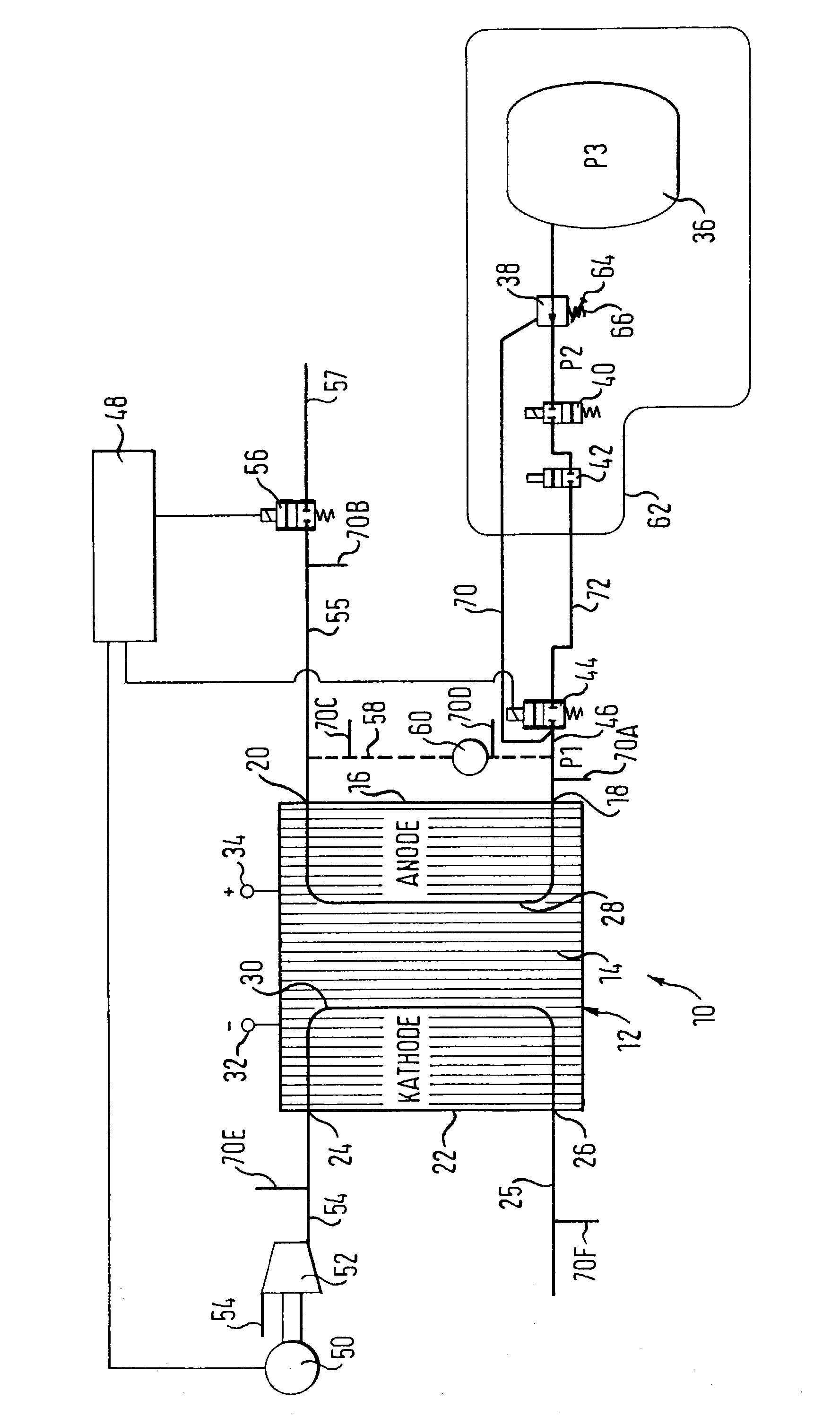
[0017]The reference numeral 10 designates the fuel cell system which includes a consumer in the form of a fuel cell stack 12. The fuel cell stack 12 consists of a plurality of individual fuel cells which are schematically designated by 14. The fuel cell stack 12 has an anode side 16 with an anode inlet 18 and an anode outlet 20 and also a cathode side 22 with a cathode inlet 24 and a cathode outlet 26.

[0018]In manner known per se each individual fuel cell 14 has an anode, a cathode and between them a membrane (not shown) with each of the so-called MEAs (Membrane Electrode Assemblies) consisting of an anode and cathode in the membrane between two so-called bipolar plates (likewise not shown). Flow passages for oxygen or atmospheric oxygen are provided between the one bipolar plate and the cathode while flow passages which serve for the supply of hydrogen to the anode are likewise provided between the other bipolar plate and the anode.

[0019]The flow passages at the anode side of the f...


PUM

PropertyMeasurementUnit
pressureaaaaaaaaaa
pressureaaaaaaaaaa
pressure P3aaaaaaaaaa

Abstract

A delivery system for the delivery of a gaseous fuel such as for example hydrogen, to a consumer, in particular to a fuel cell stack, wherein the fuel comes from a source with a higher pressure level, the delivery system comprising at least one mechanical pressure regulating valve which has a valve member biased by means of a spring and which is designed to regulate the fuel from the higher pressure level down to a lower pressure level which serves as the feed pressure for a control valve, wherein the control valve is connectable via a feed line to a consumer and determines the mass flow of the fuel coming from the source which is supplied to the consumer and wherein changes of the pressure prevailing at the consumer side of the control valve arise with power changes of the consumer, is characterized in that the said pressure prevailing at the consumer side of the control valve, or a value proportional to the latter or corresponding to it, can be supplied via a control line to the mechanical pressure regulating valve to supplement the spring bias acting on the valve member of the mechanical pressure regulating valve. In addition, a fuel cell system and a method for delivering a gaseous fuel are claimed.

Description

CROSS-REFERENCE TO RELATED APPLICATION[0001]This application claims priority in and the benefit of German Application No. 102 00 058.1 filed 02 Jan. 2002.TECHNICAL FIELD[0002]The present invention relates to a delivery system for the delivery of a gaseous fuel such as for example hydrogen, to a consumer, in particular to a fuel cell stack, wherein the fuel comes from a source with a higher pressure level, the delivery system comprising at least one mechanical pressure regulating valve which has a valve member biased by a spring and which is designed to regulate the fuel from the higher pressure level down to a lower pressure level which serves as the feed pressure for a control valve, with the control valve being connectable via a feed line to a consumer and determining the mass flow of the fuel coming from the source which is supplied to the consumer and with changes of the pressure prevailing at the consumer side of the load valve arising with power changes of the consumer. The in...

Claims


Application Information

Patent Timeline
Patent Type & Authority Patents(United States)
IPC IPC(8): H01M8/04H01M8/06H01M8/04089
CPCH01M8/04089Y02E60/50
Inventor WILLIMOWSKI, PETERSCHWAN, MIRKO
Owner GM GLOBAL TECH OPERATIONS LLC
Why Eureka
Try Eureka