Methods, devices and compositions for depositing and orienting nanostructures

a nanostructure and nano-structure technology, applied in the direction of nanoinformatics, polycrystalline material growth, crystal growth process, etc., can solve the problems of virtually all nanomaterials, affecting virtually all nanomaterials, and integrating these materials into devices and/or systems

Active Publication Date: 2006-06-27
ONED MATERIAL INC
View PDF11 Cites 118 Cited by
  • Summary
  • Abstract
  • Description
  • Claims
  • Application Information

AI Technical Summary

Benefits of technology

[0009]A number of uses, applications and variations to the invention will be readily apparent from the following disclosure, and are generally encompassed within the invention.

Problems solved by technology

While nanotechnology advances have produced materials with myriad interesting properties with broad potential applicability, the integration of these materials into useful devices, systems and materials has remained somewhat of a stumbling block when viewed from the perspective of commercial manufacturability.
This is because these nanotubes often have unpredictable electrical properties from one nanotube to the next, requiring a sensitive selection process in order to be able to use them reproducibly for more exacting requirements, e.g., in electronics, etc.
Another difficulty that affects virtually all nanomaterials is the integration of these materials into devices and / or systems where placement of such materials is important, e.g., bridging electrical contacts, spanning gate electrodes, etc.
In particular, these materials are so small that it is virtually impossible to accurately position them using manual manipulative techniques, particularly from a commercial manufacturing standpoint, e.g., in large quantities with high yields.
Despite the reported effectiveness of these methods in positioning nanomaterials, to date such methods have yielded widely disparate results, e.g., in the uniformity of the deposition, orientation and positioning of the materials.
The lack of uniformity is very detrimental in a commercial manufacturing setting, particularly when applied to, e.g., the electronics industry where product to product variations must be virtually non-existent.
These methods also suffer from manufacturing requirements that will require substantial infrastructure development as well as development of an “art” form in the performance of these techniques.

Method used


Image

  • Methods, devices and compositions for depositing and orienting nanostructures
  • Methods, devices and compositions for depositing and orienting nanostructures
  • Methods, devices and compositions for depositing and orienting nanostructures

Examples


examples

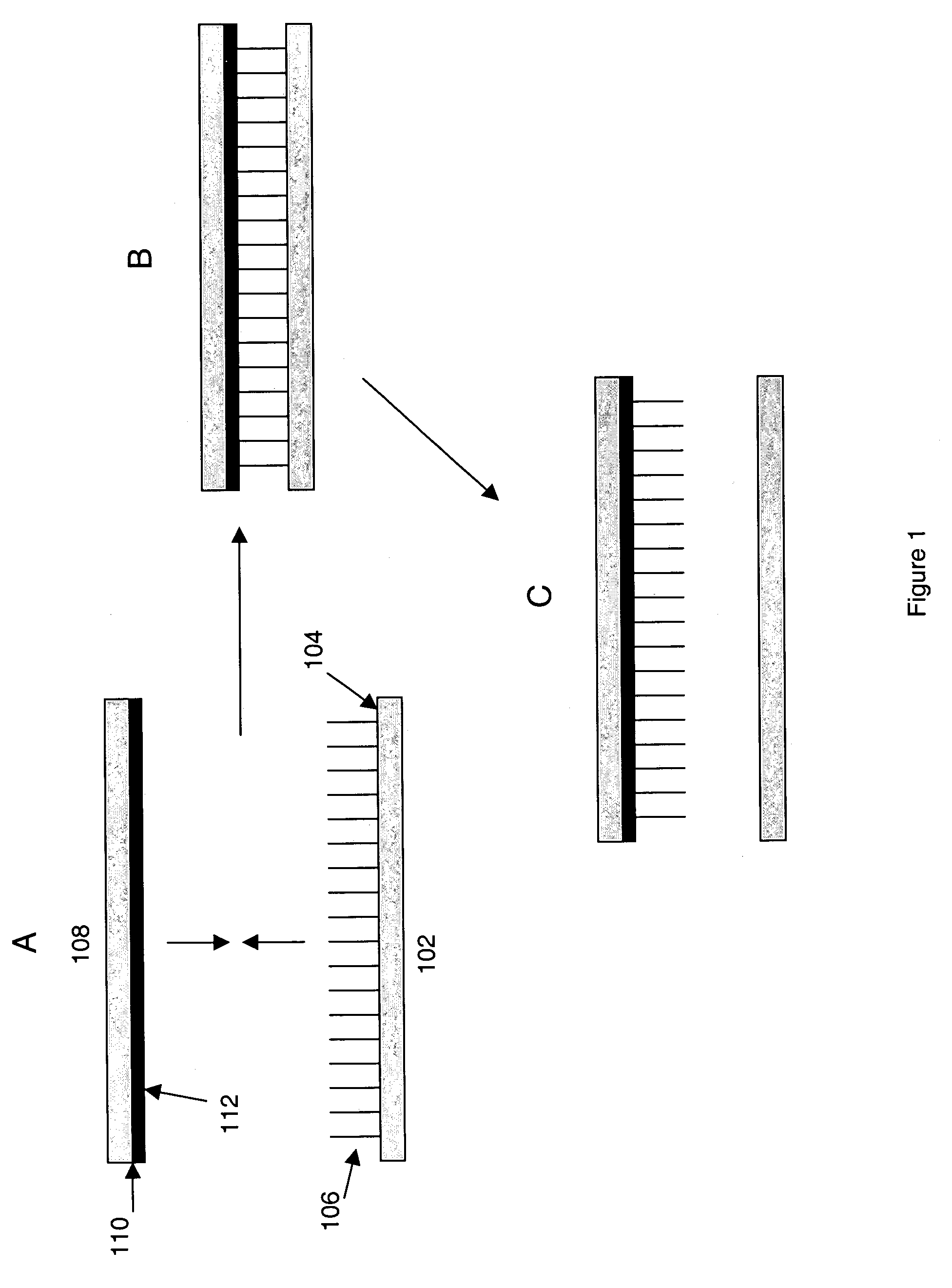
[0057]The methods described herein were employed in depositing nanowires onto a substrate in a substantially aligned orientation. In particular, a 4″ silicon wafer was used as the receiving substrate and patterned with a solution of a pressure sensitive adhesive (PolySciences 534028 in 30% isopropanol) with spots of adhesive that measured approximately 50 μm in diameter. Spotting was carried out using a standard XYZ robot and pipettor. Once deposited, the spots were dried at 60° C. to form adhesive pads about 10 μm thick on the surface of the wafer.

[0058]The transfer substrate was prepared on another 4″ silicon wafer using the standard gold colloid based CVD growth process as generally described by Lieber et al. (See, e.g., US 2003-0089899-A1). The resultant transfer wafer possessed a covering of nanowires that each generally measured approximately 40 nm in diameter and 40 μm in length (as approximated from SEM inspection).

[0059]The wire surface of the transfer wafer was set down up...


PUM

PropertyMeasurementUnit
aspect ratioaaaaaaaaaa
diameteraaaaaaaaaa
thickaaaaaaaaaa

Abstract

Methods and systems for depositing nanomaterials onto a receiving substrate and optionally for depositing those materials in a desired orientation, that comprise providing nanomaterials on a transfer substrate and contacting the nanomaterials with an adherent material disposed upon a surface or portions of a surface of a receiving substrate. Orientation is optionally provided by moving the transfer and receiving substrates relative to each other during the transfer process.

Description

BACKGROUND OF THE INVENTION[0001]Nanotechnology has been heralded as the next major technological leap, in that it is prophesied to yield a variety of substantial advantages in terms of material characteristics, including electronic, optical and structural characteristics. Some have predicted that advances in nanotechnology are the best hope for extending the lifespan of Moore's law.[0002]While nanotechnology advances have produced materials with myriad interesting properties with broad potential applicability, the integration of these materials into useful devices, systems and materials has remained somewhat of a stumbling block when viewed from the perspective of commercial manufacturability. By way of example, carbon nanotubes, often viewed as the hallmark of nanomaterials, are largely unusable from a commercial standpoint as anything more than filler for composite materials, e.g., to impart structural, and perhaps crude electrical properties to the overall bulk composite. This i...

Claims


Application Information

Patent Timeline
Patent Type & Authority Patents(United States)
IPC IPC(8): H01L21/00H01L21/31B82BC30B7/00C30B21/02C30B28/06H01L21/20H01L21/36
CPCH01L21/02381H01L21/02422H01L21/02603H01L21/02656C30B7/00H01L21/02521B82Y10/00B82Y20/00B82Y30/00Y10S977/827Y10S977/762B82B3/00B82Y40/00
Inventor DUBROW, ROBERTROMANO, LINDA T.STUMBO, DAVID
Owner ONED MATERIAL INC
Why Eureka
Try Eureka