Liquid crystal display device with a touch panel

a technology of liquid crystal display and touch panel, which is applied in the direction of identification means, instruments, computing, etc., can solve the problems of insufficient contrast, insufficient contrast, undescribed liquid crystal panel is undescribed in power consumption reduction, etc., and achieves improved coordination recognition characteristics of information input device (touch panel) provided on the liquid crystal panel, good visibility, and high luminance

Inactive Publication Date: 2006-06-27
PANASONIC LIQUID CRYSTAL DISPLAY CO LTD +1
View PDF27 Cites 17 Cited by
  • Summary
  • Abstract
  • Description
  • Claims
  • Application Information

AI Technical Summary

Benefits of technology

[0023]The above objects are achieved by a liquid crystal display device in which an illumination device made of a light guide plate and a light source and a touch panel are provided or integrated on a display-surface side of a reflection type of liquid crystal panel to uniformly illuminate its entire effective display area so that a high-quality image display can be obtained and the brightness of the screen can be improved.
[0028]Furthermore, in the liquid crystal display device, a recess portion is formed on the surface of the first substrate opposed to the second substrate, and the transparent insulation film covers the recess portion to reduce unevenness of the surface over which the transparent electrode is provided.
[0029]Furthermore, in the liquid crystal display device, a printed layer for partly reflecting light is formed on the surface of the first substrate opposed to the second substrate, and the transparent insulation film covers the printed layer to reduce unevenness of the surface over which the transparent electrode is provided.
[0044]In any of the above-described liquid crystal display devices according to the present invention, the coordinate recognition characteristics of the information input device (touch panel) provided on the liquid crystal panel are improved.
[0045]In addition, any of the above-described liquid crystal display devices according to the present invention can be applied, irrespective of the kind of liquid crystal panel (a passive matrix, active matrix and any other types of liquid crystal panels) and the screen size thereof, so that an image of good visibility which has high luminance and is uniform over its entire effective display area can be obtained even in an environment in which the external light is insufficient.

Problems solved by technology

The above-described liquid crystal panel is undesirably limited in reduction in power consumption because the two transparent substrates 1A and 1B arc used and the backlight installed on the back surface of the lower transparent substrate 1B is normally on.
However, this type of device has the disadvantage that an insufficient contrast is obtained.
However, in an environment in which external light, is insufficient, the contrast is insufficient as well.
An illumination device may be installed to solve this problem, but unlike the semi-transmission type of liquid crystal display device, an illumination device cannot be installed on the back surface of the liquid crystal panel in the reflection type of liquid crystal display device.
However, it is meaningless to apply the illumination device to a liquid crystal display device which uses a reflection type of liquid crystal panel positively utilizing external light in the above-described manner.
However, in the reflection type of liquid crystal display device which uses external light as illumination light, a display is difficult to identify in a dark environment in which the external light is insufficient.
However, in the arrangement disclosed in Japanese Patent Application No. 351794 / 1997, since the surface of an illumination-and-touch panel on which a light guide is provided is not flat, the connection between electrodes of the touch panel is far from good.
In addition, in the arrangement disclosed in Japanese Patent Application No. 351794 / 1997, the surface on which the light guide is provided needs to be formed into a staircase-like shape so that the light of a light source is guided to the liquid crystal panel, with the result that the surface on which the light guide is provided cannot be made flat.

Method used


Image

  • Liquid crystal display device with a touch panel
  • Liquid crystal display device with a touch panel
  • Liquid crystal display device with a touch panel

Examples


first embodiment

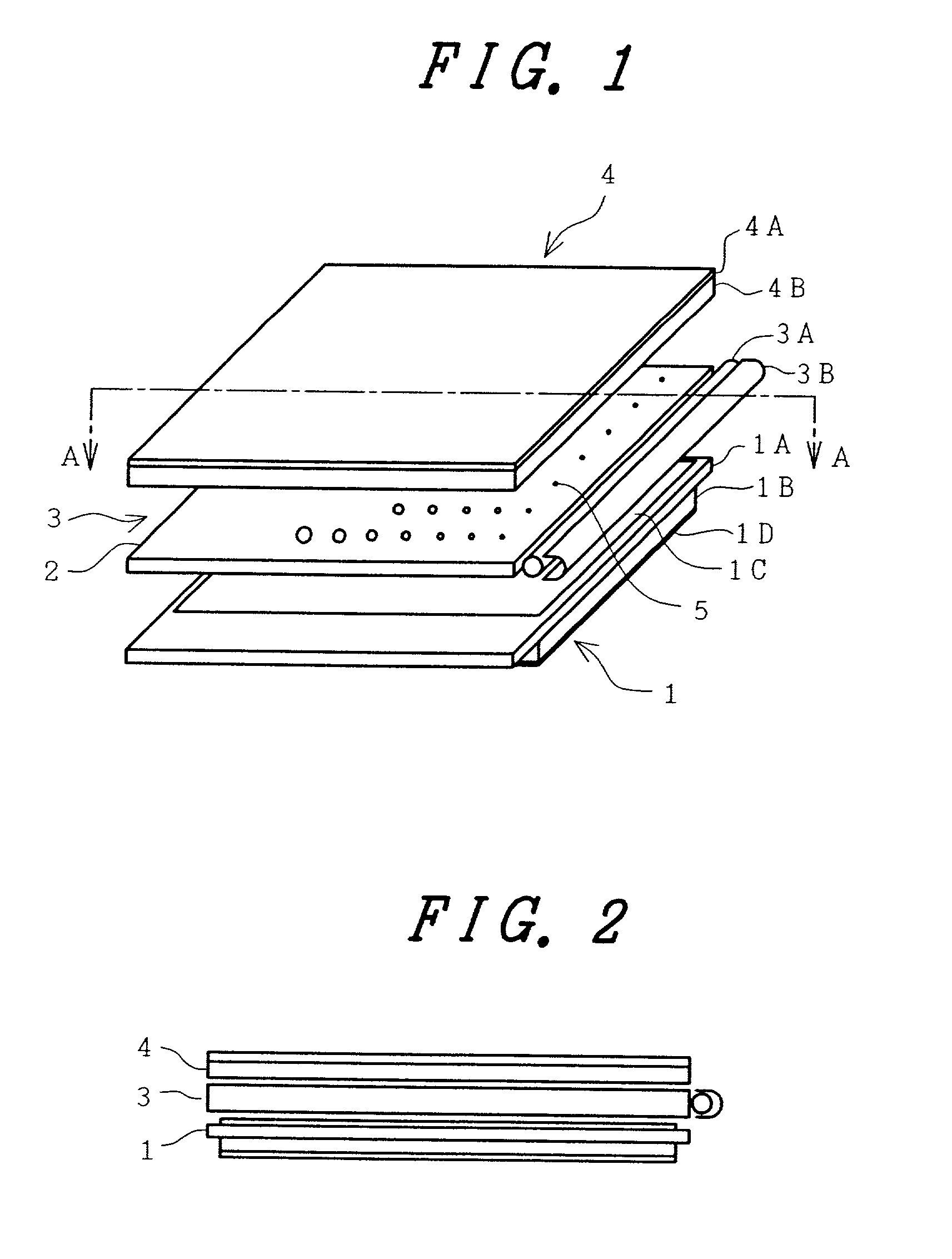
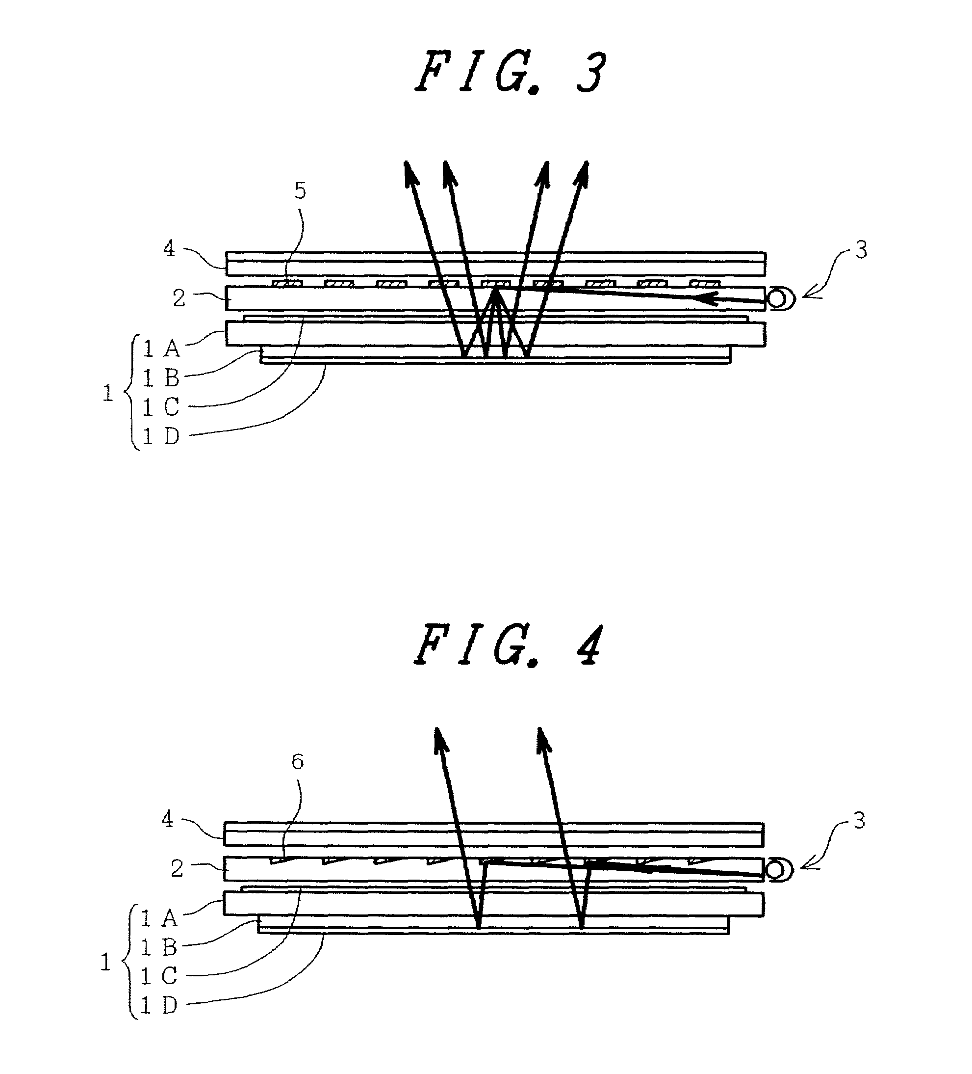
[0073]FIG. 1 is a developed perspective view illustrating the construction of a first embodiment of the liquid crystal display device according to the present invention, and FIG. 2 is a diagrammatic cross-sectional view taken along line A—A of FIG. 1. Reference numeral 1 denotes a reflection type of liquid crystal panel, reference numeral 1A denotes an upper transparent substrate, reference numeral 1B denotes a lower transparent substrate, reference numeral 1C denotes a polarizer, and reference numeral 1D denotes a reflector. Incidentally, in this embodiment, a transparent substrate is used as the lower substrate and the reflector is installed on the back surface of the lower substrate, but reflection processing may also be applied to the inner surface of the lower substrate.

[0074]Reference numeral 2 denotes a light guide plate which is made of acrylic material or the like and constitutes an illumination device, reference numeral 3 denotes an illumination device, reference numeral 3...

second embodiment

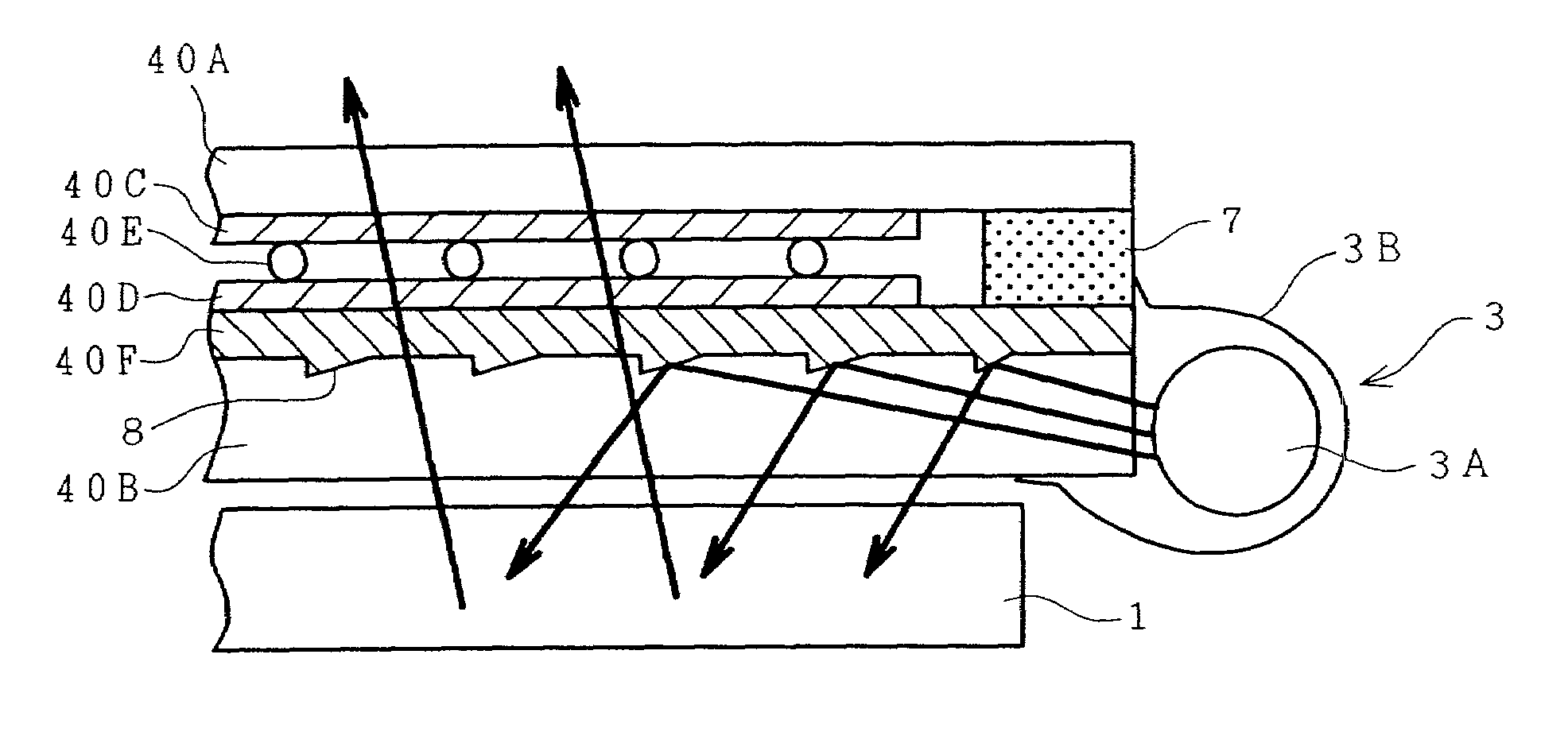
[0084]FIG. 5 is a developed perspective view illustrating the construction of a second embodiment of the liquid crystal display device according to the present invention, and FIG. 6 is a diagrammatic cross-sectional view taken along line B—B of FIG. 5. In the present embodiment, an illumination light source and a touch panel which are stacked on the liquid crystal panel 1 are integrated to reduce the thickness of the entire liquid crystal display device. Reference numerals which are identical to those used in FIGS. 1 and 2 denote functional portions identical to those of the first embodiment. Reference numeral 40 denotes an illumination-and-touch panel, reference numeral 40A denotes a transparent soft sheet which serves as the upper substrate of the touch panel, and reference numeral 40B denotes a transparent hard substrate which serves as both the lower substrate of the touch panel and a light guide plate for the illumination light source.

[0085]This transparent hard substrate 40B i...

third embodiment

[0100]FIG. 9 is a diagrammatic plan view illustrating a third embodiment of the liquid crystal display device according to the present invention, and illustrates one example of a light scattering reflection printed pattern formed on the surface of the lower transparent hard substrate of the touch panel. The present embodiment is as a whole similar to the second embodiment shown in FIG. 5, and only the form of the surface treatment formed on the surface of the lower transparent hard substrate of the illumination-and-touch panel differs between the third embodiment and the second embodiment.

[0101]As shown, a multiplicity of light scattering reflection printed patterns 9 are formed on the upper surface of the lower transparent hard substrate 40B which constitutes the illumination-and-touch panel. A transparent resin film similar to that shown in FIG. 7 is formed over the light scattering reflection printed patterns 9.

[0102]In addition, in the present embodiment, the luminance of light ...


PUM

PropertyMeasurementUnit
thicknessaaaaaaaaaa
diameteraaaaaaaaaa
diameteraaaaaaaaaa

Abstract

A liquid crystal display device including a liquid crystal display panel having a first surface for displaying an image and a second surface different from the first surface, and a position information input device provided on a first-surface side of the liquid crystal display panel. The position information input device is made of a first substrate and a second substrate more easily deformable than the first substrate. A transparent insulation film is formed over a surface of the first substrate opposed to the second substrate, a first transparent electrode is provided on the transparent insulation film, and the transparent insulation film is located between the first substrate and the first transparent electrode.

Description

CROSS REFERENCE TO RELATED APPLICATION[0001]This is a continuation of U.S. application Ser. No. 09 / 352,359, filed Jul. 13, 1999, now U.S. Pat. No. 6,456,279, the subject matter of which is incorporated by reference herein.BACKGROUND OF THE INVENTION[0002]The present invention relates to a liquid crystal display device and, more particularly, to a liquid crystal display device in which an illumination light source and a touch panel are stacked on a reflection type of liquid crystal panel which modulates light incident from its display-surface side and allows the modulated light to exit toward the display-surface side.[0003]In recent years, so-called liquid crystal display devices using liquid crystal panels have been widely used as display devices which serve as monitors for image reproducing apparatus or various information terminals.[0004]In general, such a liquid crystal display device uses a passive matrix type of liquid crystal panel which is known as an STN type, or an active m...

Claims


Application Information

Patent Timeline
Patent Type & Authority Patents(United States)
IPC IPC(8): G09G5/00H01H13/02G02F1/133G02F1/1333G02F1/1335G02F1/13357G06F3/033G06F3/041G06F3/048G09F9/00H01H13/712
CPCG02F1/13338G06F3/0488G06F3/0414G06F3/041G02F2001/133616G06F3/0412G06F3/045G02F1/133616G02F1/1335
Inventor KUBO, KIICHIRONAGASHIMA, YOSHIKUNISUZUKI, MASARUSAITO, TERUNORI
Owner PANASONIC LIQUID CRYSTAL DISPLAY CO LTD
Why Eureka
Try Eureka