Stationary computed tomography system with compact x ray source assembly

a computed tomography and compact technology, applied in tomography, applications, instruments, etc., can solve the problems of significant thermal and structural risks, limit scanning speed,

Inactive Publication Date: 2006-06-27
GENERAL ELECTRIC CO
View PDF14 Cites 56 Cited by
  • Summary
  • Abstract
  • Description
  • Claims
  • Application Information

AI Technical Summary

Problems solved by technology

Current third generation CT systems involve rotating an x ray source around the patient to do body scans and have limitations regarding scanning speeds.
The Stationary CT concept presents unique challenges in the target and geometric design of the compact x ray prod...

Method used


Image

  • Stationary computed tomography system with compact x ray source assembly
  • Stationary computed tomography system with compact x ray source assembly
  • Stationary computed tomography system with compact x ray source assembly

Examples


Embodiment Construction

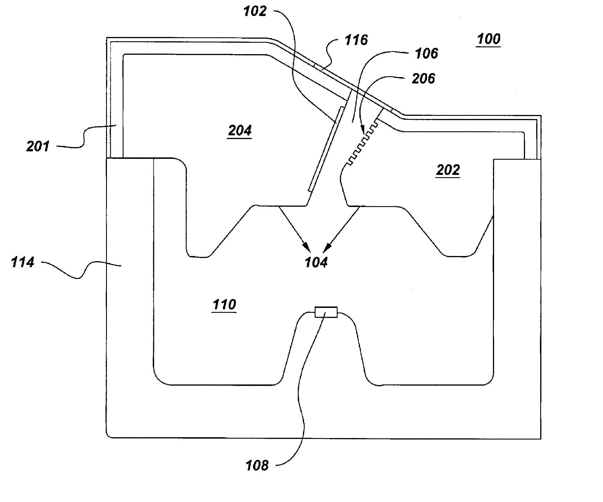
[0019]The present invention describes suitable stationary CT embodiments which combine the primary source components including a stationary x ray target 102, an electron beam source 108, an electron beam focusing chamber 104 and high heat flux cooling into a compact form and thereby enable stationary CT introduction.

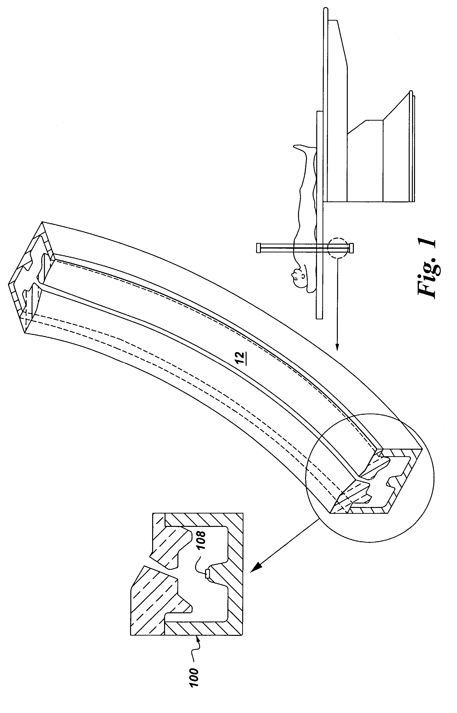
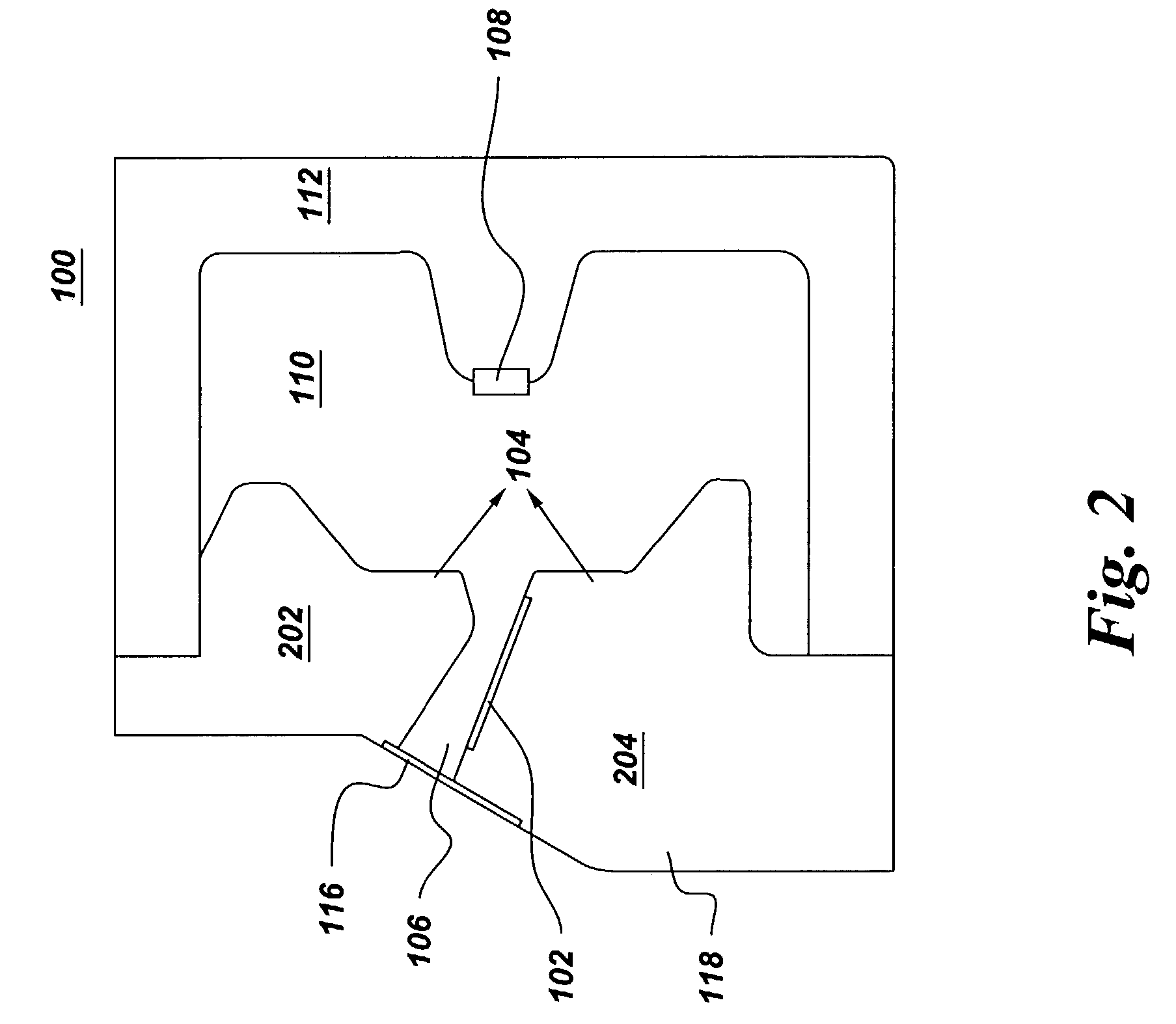
[0020]FIG. 1, illustrates a sectional view of stationary CT system 10 which, in one embodiment, comprises at least one annular x ray source assembly 12 comprising a plurality of respective x ray sources 100 spaced along the annular x ray source assembly 12. In one specific embodiment as illustrated in FIG. 2, each of the x ray sources 100 comprises a respective stationary x ray target 102, an electron beam focusing chamber 104, an x ray channel 106, and an electron beam source 108 disposed in a spaced apart relationship with respect to the respective stationary x ray target 102. The spaced apart relationship is such that the electron beam emanating from the electron beam...


PUM


Abstract

A stationary CT system comprising at least one annular x ray source assembly comprising a plurality of respective x ray sources spaced along the annular x ray source assembly. Each of the x ray sources comprises a respective stationary x ray target, an electron beam focusing chamber; an x ray channel; an electron beam source disposed in a spaced apart relationship with respect to the respective stationary x ray target; a vacuum chamber disposed in between the electron beam focusing chamber and an insulating chamber where the insulating chamber houses the electron beam source; a radiation window at a pre-defined angular displacement from the respective stationary x ray target and the x ray channel; and a target substrate attached to the respective stationary x ray target.

Description

BACKGROUND OF THE INVENTION[0001]The present invention relates generally to a Computed Tomography (CT) system and specifically to a stationary CT system with a compact x ray source assembly.[0002]Computed tomography (CT) is a technique which creates two-dimensional cross-sectional images from three-dimensional body structures. The CT imaging system primarily includes a CT gantry and a patient table or a couch. The gantry is a moveable frame that contains a x-ray source which is typically a x ray tube including collimators and filters, detectors, data acquisition system (DAS), rotational components including slip ring systems and all associated electronics such as gantry angulation motors and positioning laser lights.[0003]In known third generation CT systems (spiral / helical), the x ray source and the detector array are rotated with a gantry within the imaging plane and around the object to be imaged so that the angle at which the x ray beam intersects the object constantly changes. ...

Claims


Application Information

Patent Timeline
IPC IPC(8): A61B6/00G01N23/083G21K1/10H01J35/00G21K1/00A61B6/03G21K5/08H01J35/08H01J35/12H01J35/14
CPCA61B6/032A61B6/035A61B6/4028H01J35/14A61B6/4488H01J35/08H01J35/12A61B6/4275H01J35/13H01J35/147
Inventor KOLLEGAL, MANOHAR GOPALASWAMYWILSON, COLIN RICHARDBEWLAY, BERNARD PATRICKBENZ, MARK GILBERT
Owner GENERAL ELECTRIC CO
Why Eureka
Try Eureka