
Method and apparatus for thermo-optic modulation of optical signals

a technology of thermo-optic modulation and optical signals, applied in the field of photonic crystals, can solve the problems of consuming a large amount of power, and a large footprint of conventional thermo-optic switches such as mach-zehnder switches, and achieving a modulation speed of a few khz, consuming approximately 100 mw of power, and a few centimeters in diameter

Inactive Publication Date: 2006-06-27
GLOBALFOUNDRIES U S INC
View PDF6 Cites 20 Cited by
  • Summary
  • Abstract
  • Description
  • Claims
  • Application Information

AI Technical Summary

Benefits of technology

The present invention is a way to control the temperature of optical signals using photonic crystal structures. It involves using a special waveguide that has two electrical contacts, which are positioned close to the waveguide. By heating up one of these contacts, the temperature of the waveguide is changed, which in turn changes the refractive index. This change affects the signal that is sent through the waveguide, making it possible to control the optical signal. The technical effect of this invention is to provide a more precise and efficient way to control optical signals, which can be useful in various applications such as optical communication systems or sensors.

Problems solved by technology

Conventional thermo-optic switches such as Mach-Zehnder switches, while effective, tend to be relatively large and slow devices that consume a great deal of power.
For example, typical Mach-Zehnder switches have a footprint of several centimeters, a modulation speed of a few KHz, and consume approximately 100 mW of power.

Method used


Image

  • Method and apparatus for thermo-optic modulation of optical signals
  • Method and apparatus for thermo-optic modulation of optical signals
  • Method and apparatus for thermo-optic modulation of optical signals

Examples


Embodiment Construction

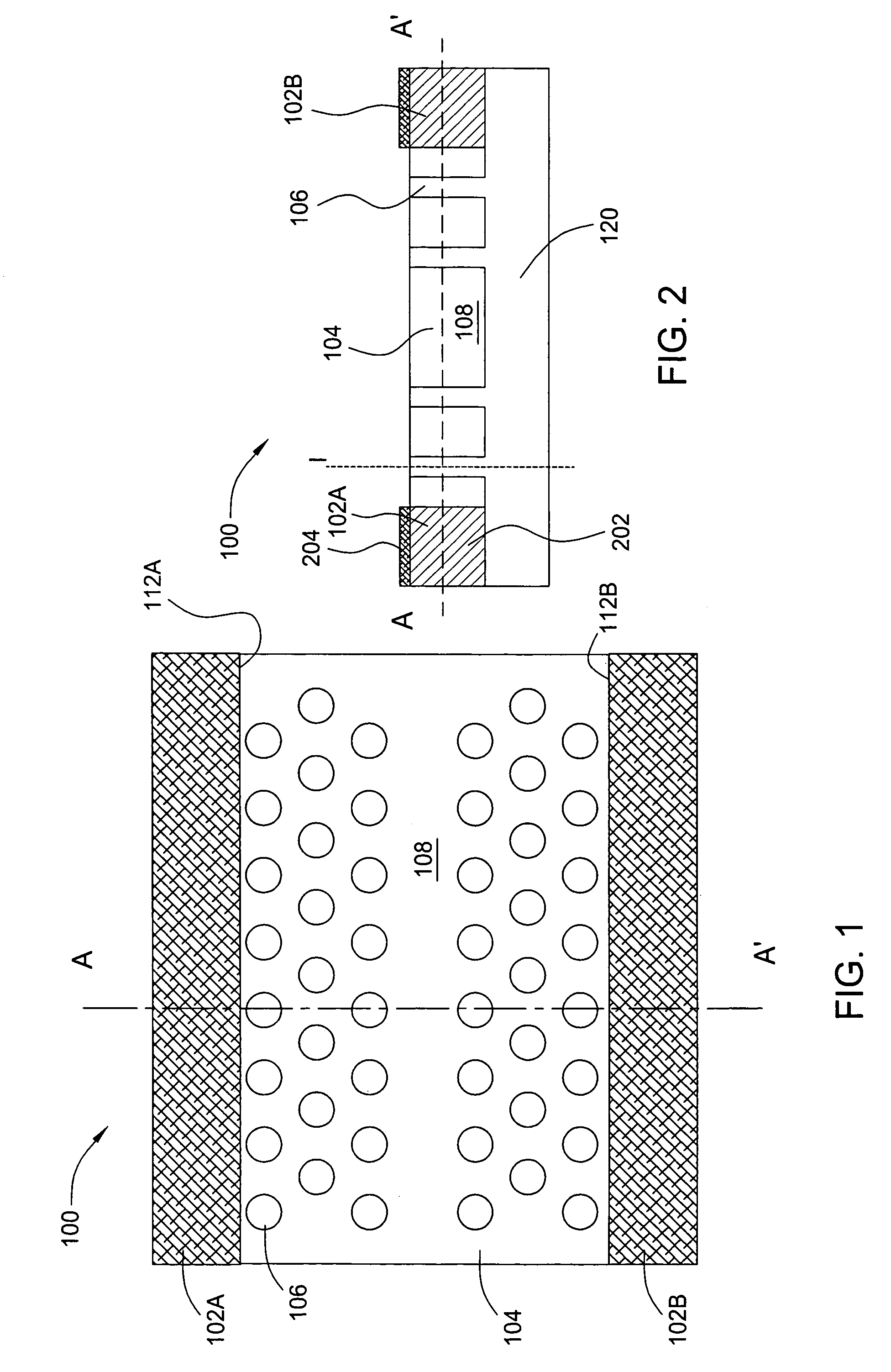
[0025]FIG. 1 is a top plan view of one embodiment of a two-dimensional photonic crystal waveguide structure 100 with lateral contacts 102a and 102b (hereinafter collectively referred to as “contacts 102”) according to the present invention. The photonic crystal structure 100 comprises a substrate 104, a plurality of apertures 106 formed in the substrate 104, a linear defect, e.g., a waveguide 108, and first and second lateral electrical contacts 102a and 102b. As illustrated in FIG. 2, which is a cross-sectional view of the photonic crystal structure 100 taken along line A–A′ of FIG. 1, the apertures 106 extend substantially completely through the substrate 104 (i.e., like channels) to an optical isolation layer 120, and the apertures 106 are arranged in rows to form a periodic lattice. The waveguide 108 is positioned to form a sort of channel through the lattice structure, with several rows of apertures 106 extending outward from the longitudinal edges of the waveguide 108. The fir...


PUM

PropertyMeasurementUnit
aperture-radiusaaaaaaaaaa
wavelengthaaaaaaaaaa
thicknessaaaaaaaaaa

Abstract

The present invention is a method and an apparatus for thermo-optic control of optical signals using photonic crystal structures. In one embodiment, a first portion of a split signal is modulated by propagating the signal through a photonic crystal waveguide in which two electrical contacts are laterally spaced from the waveguide region by a plurality of apertures formed through the photonic crystal substrate. A voltage applied across the electrical contacts causes resistive heating of the proximate photonic crystal waveguide through which the signal propagates, thereby modulating the temperature relative to an un-modulated second portion of the split signal that is used as a reference.

Description

CROSS REFERENCE TO RELATED APPLICATIONS[0001]This application is a continuation-in-part of co-pending, commonly assigned U.S. patent application Ser. No. 10 / 686,216, filed Oct. 15, 2003 by Hamann et al., which is herein incorporated by reference in its entirety.BACKGROUND[0002]The invention relates generally to photonic crystals, and relates more particularly to the tuning, modulation and switching of optical signals in integrated photonic crystal devices. Specifically, the present invention relates to a method and apparatus for thermo-optic modulation of optical signals using photonic crystal structures.[0003]Active manipulation of light transmission in a planar lightwave circuit can be performed by changing the temperature of a region of a planar waveguide. A temperature change results in a change the optical parameters of the planar waveguide (e.g., a change of the effective refractive index seen by the signal confined within the photonic crystal lattice, waveguide or cavity). Co...

Claims


Application Information

Patent Timeline
Patent Type & Authority Patents(United States)
IPC IPC(8): G02F1/295G02B6/122G02B6/26G02F1/01G02F1/025G02F1/035
CPCB82Y20/00G02B6/1225G02F1/011G02F1/025G02F2202/32G02F2201/12G02F1/0147G02B6/29353G02B6/26
Inventor HAMANN, HENDRIK F.MCNAB, SHAREE J.O'BOYLE, MARTIN P.VLASOV, YURII A.
Owner GLOBALFOUNDRIES U S INC
Learn More