
Computer system and a data transfer method thereof using remote direct memory access

Inactive Publication Date: 2006-06-27
HITACHI LTD
View PDF9 Cites 13 Cited by
  • Summary
  • Abstract
  • Description
  • Claims
  • Application Information

AI Technical Summary

Benefits of technology

[0009]A first object of the present invention is to decrease the overhead that is required to execute the exclusive processes impeding improvement in the data transfer efficiency.

Problems solved by technology

Therefore, this related art has a problem that it cannot be easily adapted to the real-time process due to its response time.
On the occasion of transferring a large amount of data, there is a problem that the overhead that is required for these exclusive processes becomes large in the number.
Moreover, this overhead sometimes lowers the data transfer efficiency.

Method used


Image

  • Computer system and a data transfer method thereof using remote direct memory access
  • Computer system and a data transfer method thereof using remote direct memory access
  • Computer system and a data transfer method thereof using remote direct memory access

Examples


first embodiment

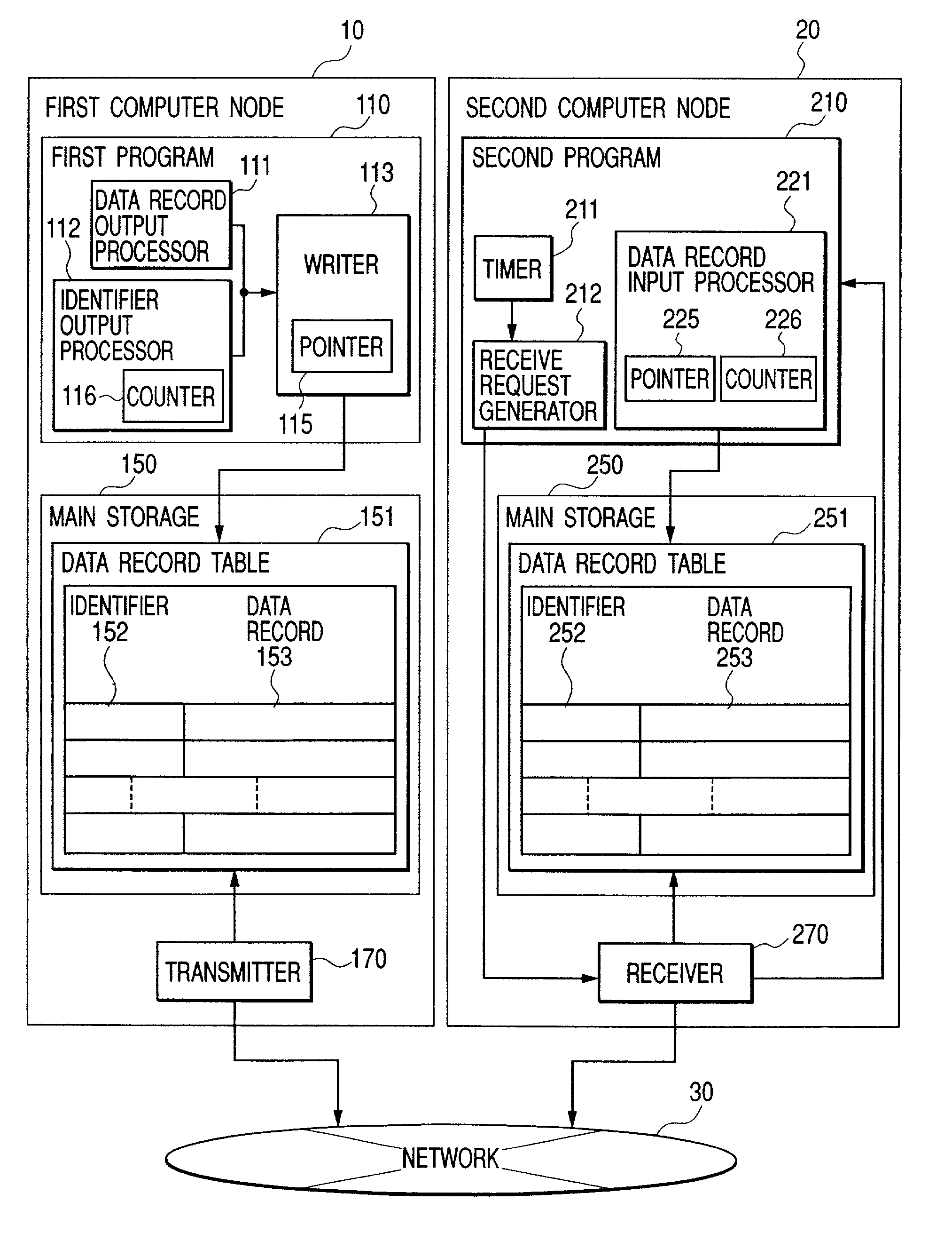
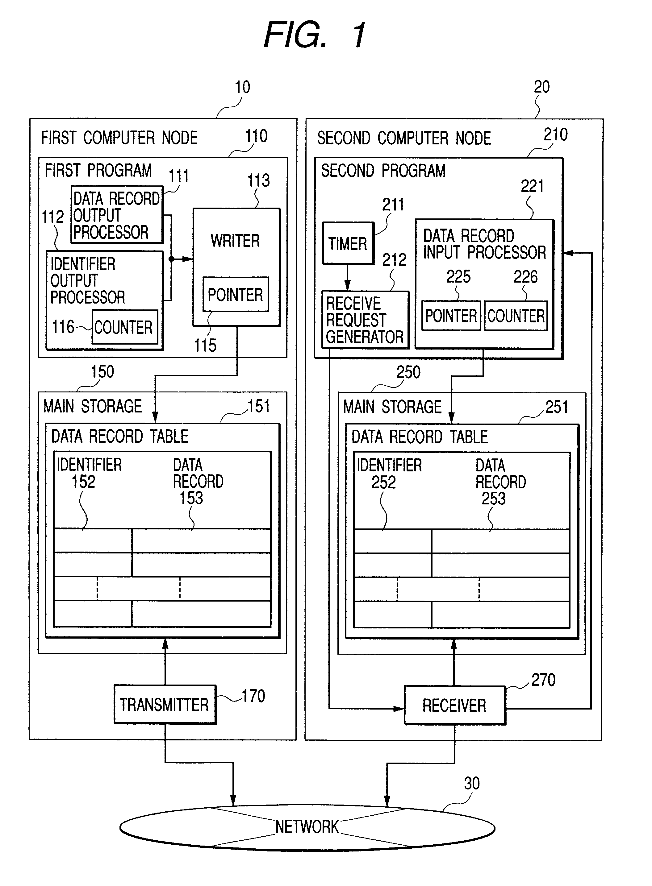
[0049]First, the present invention will be explained with reference to FIG. 1 to FIG. 10.

[0050]FIG. 1 is a total structural diagram illustrating the first embodiment of the present invention. The first computer node 10 and the second computer node 20 are connected with a network 30 and these first computer 10 and the second computer 20 are capable of making communication via the network 30.

[0051]The first computer node 10 is provided with a first program 110 for outputting a data record 153 to be transmitted to the second computer node 20, a data record table 151 stored in the main storage 150 to store the data record 153 and a transmitter 170 for transmitting the data record 153 to the second computer 20 via the network 30. The transmitter 170 is formed of a program independent of the first program 110 or of a hardware system. Moreover, the first program 110 is composed of a data record output processor 111 for outputting the data record 153, an identifier output processor 112 for ...

second embodiment

[0086]FIG. 13 illustrates the total structural diagram of the present invention. Difference from FIG. 1 is that the first program 110 includes an error checking code generator 114, the second program 210 includes a validation processor 222, the data record table 151 includes an error checking code 154 and the data record table 251 includes an error checking code 254.

[0087]The error checking code generator 114 generates the error checking code 154 from a set of the identifier 152 of data record entry and data record 153. The validation processor 222 checks whether the error checking code 254 is the code (correct) generated from a set of the identifier 252 of the data record entry and data record 253 or not (incorrect). Here, the reason why the error checking code is employed will be explained briefly. In the first embodiment, the method of detecting incorrect data by reading the data for transfer in the direction opposed to the direction for writing the data record such as journal da...

third embodiment

[0101]FIG. 19 is a total structural diagram of the present invention. Difference from FIG. 1 is that the first program 110 includes a data transmit request generator 122 and the second program 210 does not include the timer 211 and a data receive request generator 212. The data transmit request generator 122 generates a transmit request of data record table 151 to the transmitter 170. Namely, it is indicated that the data transfer is conducted under the control of the transmitter side using the RDMA-Write. In this case, the first computer node introduces the transfer system where the load is heavier than that in the structure of FIG. 1 but the synchronization is not established and therefore a load becomes smaller than that in the prior art. The data transmit request generator 122 causes the transmitter 170 to read the data when a certain amount of transmitting data is collected. Data transfer can be executed when the second program recognizes the request of data transfer through th...


PUM


Abstract

In the data transfer method between a couple of computer nodes in the related art, an overhead for the waiting between programs to conduct the data transfer is considerably large.In the present invention, a first program to transmit data stores the data to the main storage area in the desired time interval. A second program to receive data refers to the above area using RDMA in the desired time interval. Otherwise, the second program to receive data refers to the main storage in the desired time interval. A first program to transmit data stores data to above area using RDMA in the desired time interval. Moreover, in order to detect the passing between the write and read operations, an identifier is provided to each record and the access sequence of the identifier and record is inverted in the read and write operations. Or, an identifier and an error checking code are added to each record.

Description

BACKGROUND OF THE INVENTION[0001]1. Field of the Invention[0002]The present invention relates to the process to transfer the data consisting of a plurality of records among the computers connected with a network or an input / output channel[0003]2. Description of the Related Art[0004]Following two kinds of technologies have been proposed as the prior arts for transferring the data consisting of many records between a couple of computer nodes.[0005]The first related art is described from the line 61 to the line 81 on the page 2 of the Japanese Laid-Open Publication No. H6-67944. This first related art discloses a method of using a common disc drive for a couple of computer nodes. In this method, a set consisting of two volumes storing the same data is prepared and each volume is respectively connected to each computer node for the purpose of common use. When one computer node desires to refer to the data, it releases the set of volumes (separation of volumes) and causes the computer no...

Claims


Application Information

Patent Timeline
IPC IPC(8): G06F15/16G06F15/167H04L29/06
CPCH04L67/1097H04L29/06H04L9/40
Inventor SERIZAWA, KAZUYOSHINAGASUKA, HIROFUMISAKURABA, TAKETOSHININOSE, KENTAYAMASHITA, MASAHIRO
Owner HITACHI LTD
Learn More