Caution is usual required when using scouring cleaning devices, because they are capable of damaging many common surfaces.
Therefore, scouring pad cleaning devices are typically only used to clean very hard robust surfaces or where the intended result is to remove a
surface layer in a
polishing operation.
While there are clearly many options when choosing a cleaning
system, medium or device for a particular cleaning task, many of the devices and systems described above fall short of an ideal cleaning device or
system, even when they are used for their intended application.
In particular none of the prior art cleaning devices are optimized for cleaning a surface where the surface is soiled with a soft residue which is strongly adhered to the surface.
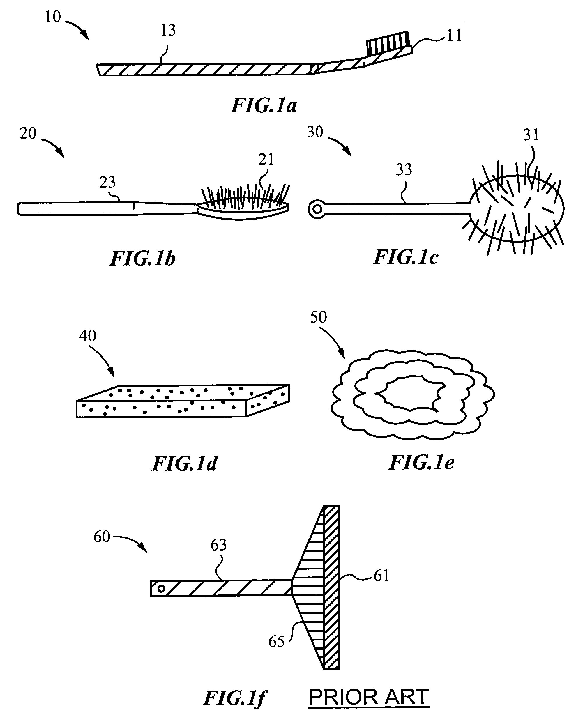
A dish
brush, when used in combination with soapy water, generally does not clean dishes, pots or pan efficiently if a food residue is strongly adhered to the surface of the dish, pot or pan.
The
brush itself does not provide for the high degree of surface contact required to remove the residue.
In cases where
soap suds and
convection have little or no effect on a residue because of its excellent adhesion properties or low
solubility in the soapy water, a
brush device generally does not efficiently clean the surface, even if the residue is soft.
Firstly, while a
sponge cleaning device will provide for more efficient surface contact than the brush, a
sponge does not always provide sufficient abrasion or surface
contact pressure required to remove a residues.
Secondly, a
sponge cleaning device is typically hand-held and usually requires the operator's hands to become immersed in the soapy water, which can be an unpleasant experience in the case of cleaning spaghetti sauce residue from the surface of a pot.
Lastly, a sponge cleaning device can become irreparably soiled and stained by residues, such as spaghetti sauce, making the sponge cleaning device a highly unattractive addition to the kitchen sink area.
A
souring pad device will generally provide sufficient abrasion and surface contact to remove residues from a surface but suffers from all other shortcomings of a sponge cleaning device.
Further, a scouring pad cleaning device may destroy or ruin the surface being cleaned, especially if the surface is a cooking pot with a non-stick
surface coating.
A second example where known cleaning devices fail to provide efficient cleaning is in cleaning porcelain surfaces.
Stains and fecal material are not readily removed from porcelain surfaces with brush cleaning devices for the same reasons that a
brush device does not efficiently remove spaghetti sauce from a pot.
A sponge cleaning device also fails to be an ideal cleaning tool for cleaning porcelain surfaces for reasons already mentioned.
A more severe limitation of brush and sponge cleaning devices for cleaning porcelain deification receptacles, is that after a
single use the cleaning devices can become unsanitary, unsightly and smelly due to residual residue material that gets stuck and is retained between the
bristle of the
brush device or is strongly absorbed within the sponge material.
Yet another situation where currently available cleaning device fail is in providing for efficient cleaning of enamel surfaces such as teeth or
dentition and the like.
A tooth brush, unfortunately, is an inefficient device for removing plaque and stains from the enamel surfaces of teeth an is poorly suited for cleaning the surfaces of gum tissue.
The inefficiency arises because plaque, while relatively soft, strongly adheres to enamel surfaces of the teeth.
Further, plaque is not readily removed from the enamel surfaces by brush
convection with water and
toothpaste.
Even where bristles of the
toothbrush contact enamel surfaces of the teeth during a cleaning operation, the
toothbrush generally fails to remove stains.
Yet another shortcoming of a toothbrush is that the toothbrush is too
abrasive for cleaning or messaging the surfaces of gum tissue.
Even if a soft bristled toothbrush is used regularly, after years of brushing, gum recession can result from toothbrush abrasion.
Temperature sensitivity of the teeth can become so severe for people with gum recession that they can not enjoy warm and hot drinks, such as coffee or tea, or eat cold treats, such as
ice cream.

