Floor tool

a technology for floor surfaces and tools, applied in the field of floor tools, can solve the problems of limited pick-up performance of such tools, less effective carpeted floors, and more expensive types of floor tools than passive ones, and achieve the effects of improving the agitation effect on the floor surface, improving the pick-up performance of tools, and improving the agitation

Inactive Publication Date: 2006-07-04
DYSON TECH LTD
View PDF20 Cites 22 Cited by
  • Summary
  • Abstract
  • Description
  • Claims
  • Application Information

AI Technical Summary

Benefits of technology

[0005]The present invention seeks to improve the pick-up performance of a passive floor tool.
[0007]It has been found unnecessary to recess the lint picker and to break the working edge in order to accommodate the lint picker. Positioning the lint picker such that it is separated from the suction channel by the working edge provides a full effective working edge which maximises agitation to the floor surface. The lint picker is also able to operate on the floor surface.
[0009]Preferably, agitation is further improved by providing a working edge with a sharply defined, angular, edge with a minimal radius of curvature. An edge having a radius of around 0.2 mm has been found to be effective.
[0010]The pick up performance of the tool is further improved by pivotably supporting the floor tool such that the working edges on each side of the suction channel are alternately brought into contact with the floor surface as the floor tool is pushed and pulled across the surface. As one of the working edges is brought into contact with the floor surface, the other raises slightly to allow air to bleed into the suction channel. This improves the agitating effect on the floor surface and reduces the motion resistance or push-force required to move the floor tool.

Problems solved by technology

While floor tools of the kind shown in FIG. 1 work well on hard floor surfaces, they are less effective on carpeted floors where hair, fluff and other fibrous material, collectively called ‘lint’, become trapped on the carpet.
However, this type of tool is more expensive than the passive floor tool.
However, the pick-up performance of such tools is limited.

Method used


Image

  • Floor tool
  • Floor tool
  • Floor tool

Examples


Embodiment Construction

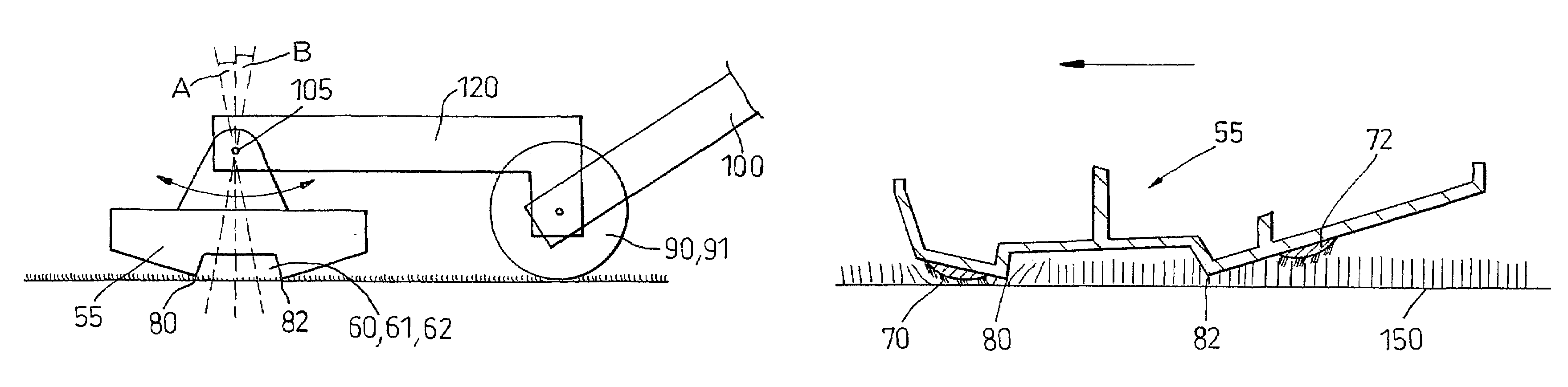
[0021]As shown in FIGS. 3 and 4, the floor tool 50 comprises a housing having a lower plate 55, or sole plate, which is intended to ride along a floor surface. The sole plate 55 is fully shown in FIG. 3. For case of understanding in the following description, the arrowed line X in FIG. 3 indicates the longitudinal direction and the arrowed line Y the transverse direction. The sole plate 55 has a centrally mounted air inlet 60 which communicates via a conduit to the outlet 100. Outlet 100 is suitably dimensioned to connect to a hose or wand of a vacuum cleaner as shown in FIG. 1. Two suction channels 61, 62 extend transversely across the tool each side of the inlet 60. Each channel decreases in depth towards the sides of the tool and terminates in an inlet 63, 64 on the side of the tool. The length of channel 61, 62 (LC) is shown here as being about one third of the total length (LT) of the tool but this proportion can be varied. The side walls 75, 76 of the channels 61, 62 are sharp...


PUM


Abstract

A floor tool for use in vacuum cleaning floor surfaces includes a sole plate that has a suction channel formed in it. The suction channel is bounded on at least one side by a working edge for engaging with the floor surface. Lint pickers are positioned alongside the suction channel and are separated from the suction channel by the working edge. The lint pickers are mounted on a surface of the floor tool which is inclined with respect to the plane in which the working edges lie. The sole plate is pivotally mounted with respect to a suction outlet so that movement of the floor tool in a forward and backwards direction alternately brings one of the working edges into closer contact with the floor surface.

Description

FIELD OF THE INVENTION[0001]This invention relates to a floor tool for use with a vacuum cleaner.BACKGROUND OF THE INVENTION[0002]Cylinder or canister vacuum cleaners, as shown in FIG. 1, generally comprise a main body 10 which contains separating apparatus 11 such as a cyclonic separator or a bag for separating dirt and dust from an incoming dirty airflow. The dirty airflow is introduced to the main body 10 via a hose 15 and wand 16 assembly which is connected to the main body 10. The main body 10 of the cleaner is dragged along by the hose as a user moves around a room. A cleaning tool 20 is attached to the remote end 17 of the hose and wand assembly. A range of cleaning tools are usually supplied so that a user can choose an appropriate tool for their cleaning task, such as crevice tool and a brush tool. The cleaning tool which is used for general cleaning is a floor tool 20. FIG. 2 shows the underside of a floor tool sold by DYSON™ and shown more fully in Registered Design GB 2,...

Claims


Application Information

Patent Timeline
Patent Type & Authority Patents(United States)
IPC IPC(8): A47L9/06A47L9/02
CPCA47L9/02A47L9/0633A47L9/0613A47L9/06
Inventor BAGWELL, MARTIN PAUL
Owner DYSON TECH LTD
Why Eureka
Try Eureka