
Recoil starter

a starter and coil technology, applied in the direction of engine starters, muscle operated starters, machines/engines, etc., can solve the problems of increased dimensions of recoil starters, engine cooling cannot be efficiently conducted, outer dimensions of the casing, etc., to reduce the pulling load of recoil ropes, the effect of reducing size and weigh

Active Publication Date: 2006-07-04
STARTING IND CO LTD
View PDF12 Cites 32 Cited by
  • Summary
  • Abstract
  • Description
  • Claims
  • Application Information

AI Technical Summary

Benefits of technology

[0008]Accordingly, it is an object of the present invention to provide a recoil starter enabling cooling air to be introduced into the inside of an engine through openings in the engine so that cooling of the engine can be efficiently conducted even when outer dimensions of a rope reel are designed to be large in order to reduce the pulling load of a recoil rope.
[0009]It is another object of the present invention to provide a recoil starter enabling the dimensions, particularly in the axial direction, of the recoil starter to be reduced so that size and weight reduction can be achieved.

Problems solved by technology

There are problems in that, when the rope reel is formed to have a large outer diameter in order to reduce the pulling load of the recoil rope, the outer dimensions of the casing also becomes large, and when the casing is mounted to the engine, openings in the engine are blocked up, so that air for cooling the engine cannot be introduced into the inside of the engine, with the result that cooling of the engine cannot be efficiently conducted.
Therefore, it is necessary to set the axial-direction dimension between the cam and the drive pulley to be large, leading to an increase in the dimension of the recoil starter in the axial direction, with the result that there is the problem that a reduction in size and weight cannot be achieved.

Method used


Image

  • Recoil starter
  • Recoil starter
  • Recoil starter

Examples


Embodiment Construction

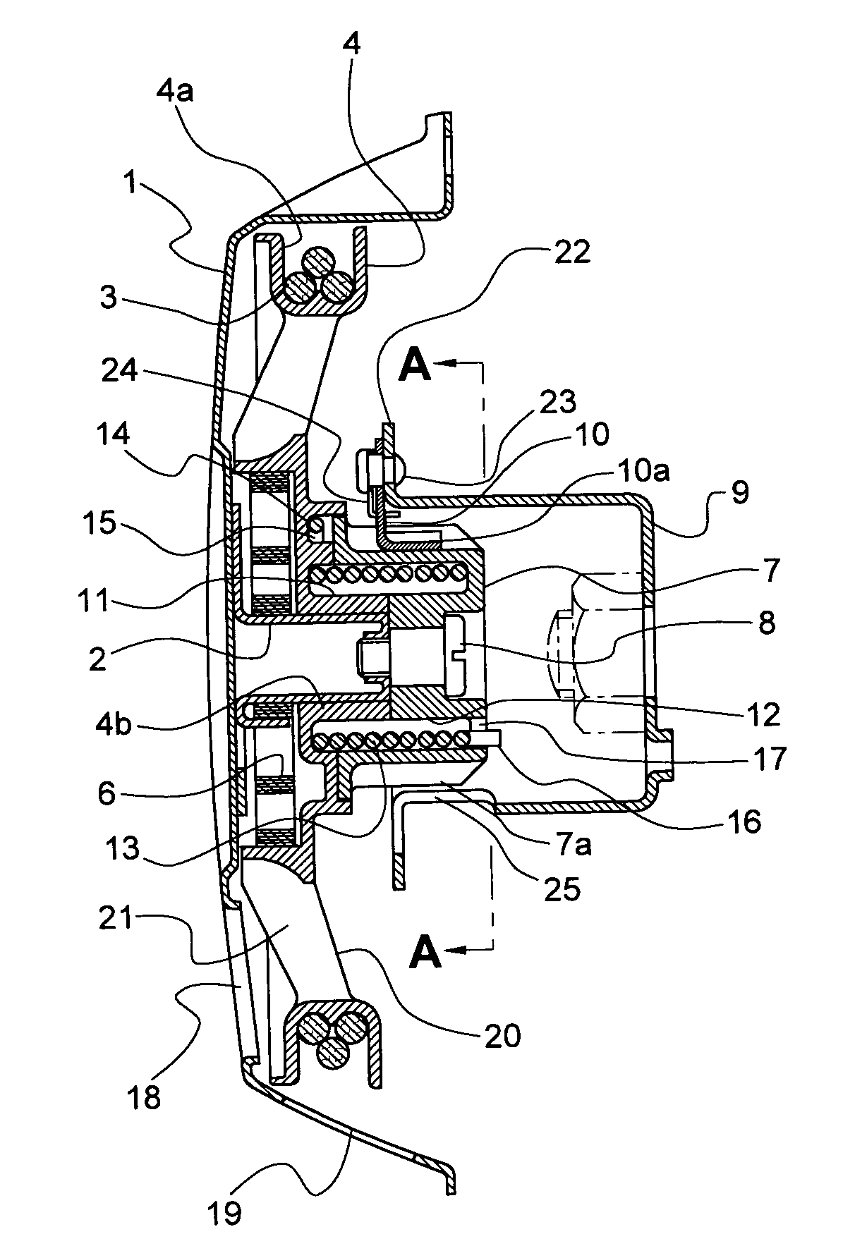
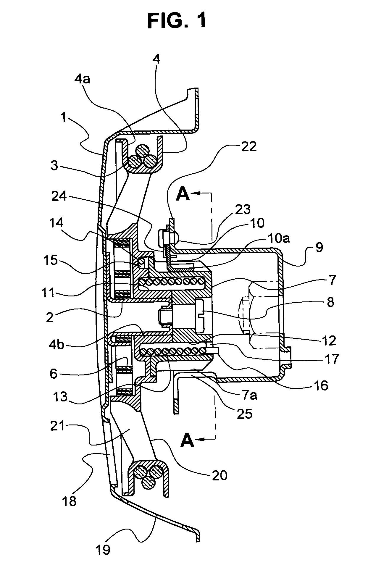
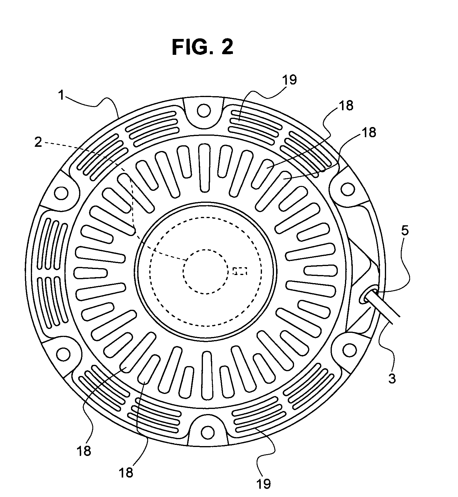
[0019]An embodiment of the invention will be described below by way of example with reference to the drawings. As shown in FIGS. 1 to 3, a recoil starter of the illustrated embodiment includes a casing 1 which is formed so as to receive therein main components of the recoil starter and cover a side surface portion of an engine. The casing 1 is provided at an inner surface of a side wall thereof with a reel shaft 2 which is formed so as to face and be coaxial with a crankshaft of the engine. A rope reel 4, which includes a drum portion 4a formed at an outer periphery thereof and which has a recoil rope 3 wound around the drum portion 4a thereof, is rotatably mounted to the reel shaft 2. One end of the recoil rope 3 wound around the drum portion 4a of the rope reel 4 is fixed to the rope reel 4 and, as shown in FIG. 2, the other end of the recoil rope 3 is pulled out to the outside of the casing 1 through an opening 5 formed in the casing 1. By pulling the other end of the recoil rope...


PUM


Abstract

A recoil starter capable of introducing cooling air into an engine through the recoil starter and reducing a size and weight thereof. Annular recesses are formed in opposing joint surfaces of a rope reel and a cam, respectively, in a manner to face each other. A damper spring is received in the annular recesses while opposite ends thereof are respectively held at the rope reel and the cam so that the rope reel and the cam are rotationally coupled together via the damper spring. Air inlets for introducing air for cooling the engine are formed in a side wall of a casing. Air passages facing the air inlets of the casing are formed between a drum portion at an outer periphery of the rope reel and a boss portion forming the annular recess of the rope reel.

Description

BACKGROUND OF THE INVENTION[0001]1. Field of the Invention[0002]The present invention relates to a recoil starter, wherein a recoil rope wound around a rope reel is pulled to rotate the rope reel so that a rotation of the rope reel is transmitted to a rotating member such as a drive pulley or the like coupled to a crankshaft of an engine via a ratchet mechanism, to thereby start the engine.[0003]2. Description of the Related Art[0004]Among recoil starters where a rotation of a rope reel rotated by pulling a recoil rope wound around the rope reel is transmitted to a cam, and a rotation of the cam is transmitted to a rotating member such as a flywheel magnet or a drive pulley coupled to a crankshaft of an engine via a clutch mechanism such as a centrifugal clutch, so that the crankshaft of the engine is rotated to start the engine, a recoil starter is known which is so constructed that the rope reel and the cam are resiliently coupled by a damper spring in the form of a spiral spring ...

Claims


Application Information

Patent Timeline
IPC IPC(8): F02N3/02F02N5/02F02N15/00
CPCF02N3/02F02N15/027F02N15/00F02N5/02
Inventor TSUNODA, SHUHEIMORISHIGE, TOSHINORI
Owner STARTING IND CO LTD
Learn More