Snowmobile suspension

a suspension and snowmobile technology, applied in the direction of axle suspension, pivoted suspension arms, cycle equipment, etc., can solve the problems of weight transfer from the front of the vehicle to the rear, interference with steering, centrifugal force imposed on the vehicle, etc., to improve the dynamic feature and limit the stroke distance

Active Publication Date: 2006-07-04
BOMBARDIER RECREATIONAL PROD INC
View PDF8 Cites 38 Cited by
  • Summary
  • Abstract
  • Description
  • Claims
  • Application Information

AI Technical Summary

Benefits of technology

[0015]The suspension assembly of the present invention advantageously provides the first or front shock absorber assembly in an operation condition with a rising rate so that in most instances the first or front shock absorber assembly will be absorbing large impacts without having the compression stroke thereof bottom out. This is desirable, particularly for the front shock absorber assembly which extends across the limited space between the slide frame assembly and the tunnel, and thus usually has a limited stroke distance.
[0016]The suspension assembly of the present invention will further improve the dynamic feature thereof when the vehicle is in acceleration. It is known that during acceleration the tension in the track pulls the rear ends of the slide rails up towards the tunnel and pushes the front ends of the slide rails onto the ground, which transfers the weight of the vehicle to the rear thereof and tends to lift the skis off the ground. In the conventional snowmobile suspension assemblies the first or front shock absorber assembly pushes the front portions of the slide rails away from the tunnel during acceleration so that the undesirable condition is aggravated. With the suspension assembly of the present invention, testing has shown that the first or front shock absorber assembly is substantially unloaded during acceleration, which allows the front ends of the slide rails to move up towards the tunnel. Therefore, less weight is transferred to the rear of the vehicle and less weight is removed from the skis so that the skis are prevented from lifting off the ground during acceleration.

Problems solved by technology

There are also internal forces developed during rapid acceleration, which causes a weight transfer from the front of the vehicle to the rear.
This tends to lift the skis off the ground and thus interferes with steering.
Furthermore, there are centrifugal forces imposed on the vehicle when the vehicle makes turns at high speeds.
Irregularities in the terrain traveled by the snowmobile produce displacements and deflections of the front suspension that supports the vehicle on the skis, and of the rear suspension.
Depending upon their magnitude, frequency and strength, these deflections cause more or less discomfort to the operator and passenger of the snowmobile.
It has been recognized that suspension displacements that produce angular acceleration of the snowmobile and its operator about a transverse horizontal axis, produce more discomfort than displacements that merely produce vertical acceleration of the vehicle and its operator.

Method used


Image

  • Snowmobile suspension
  • Snowmobile suspension
  • Snowmobile suspension

Examples


Embodiment Construction

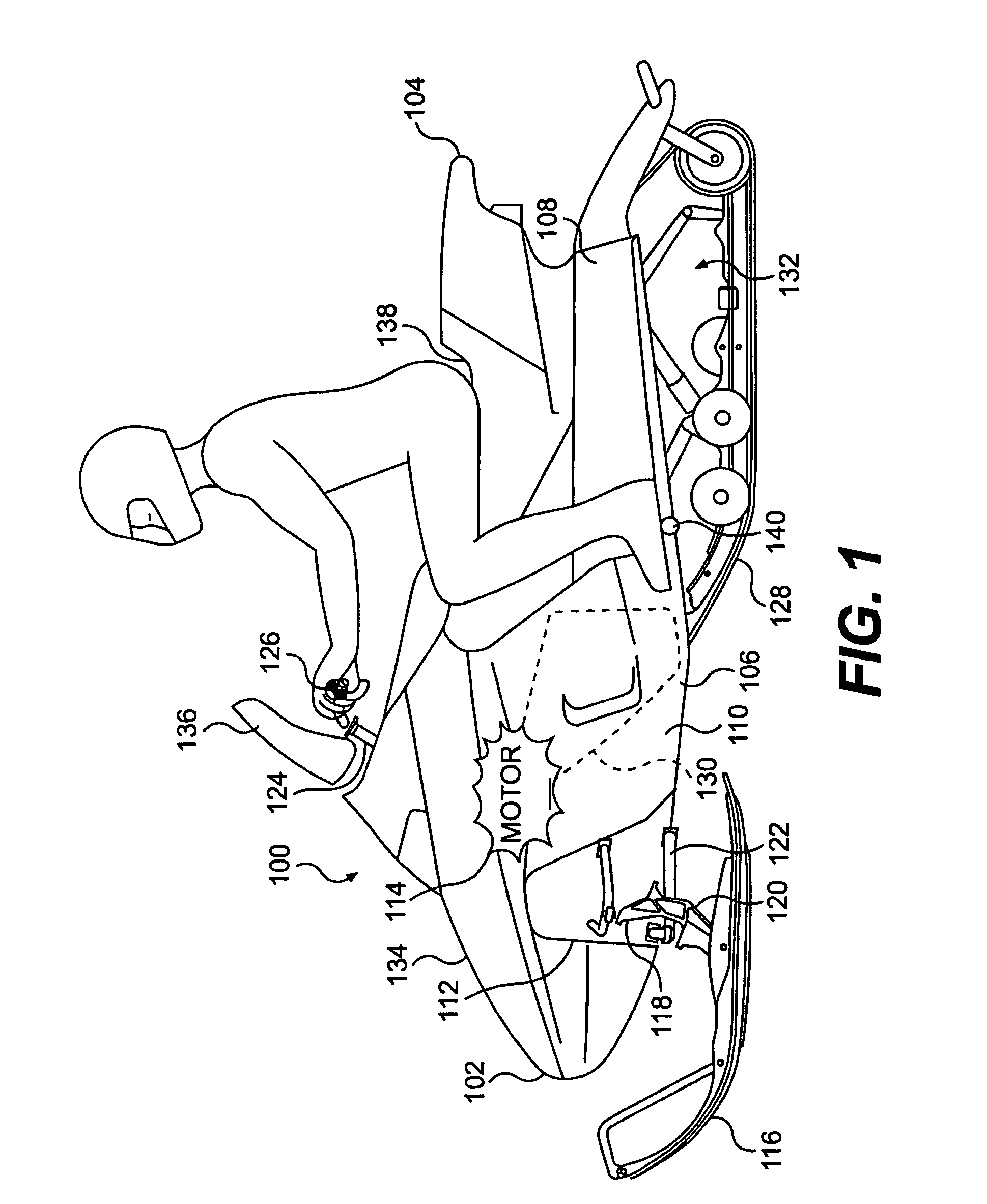
[0028]Referring now in detail to the drawings, and primarily to FIG. 1, a snowmobile incorporating the present invention is identified generally by the reference numeral 100.

[0029]The snowmobile 100 includes a forward end 102 and a rearward end 104, which are defined consistently with the forward travel direction of the vehicle. The snowmobile 100 includes a chassis 106 which normally includes a rear tunnel 108, an engine cradle portion 110 and a front suspension assembly portion 112. An engine 114 which is schematically illustrated, is carried by the engine cradle portion 110 of the chassis 106. A ski and steering assembly (not indicated) is provided, in which two skis 116 (only one is shown) are positioned at the forward end 102 of the snowmobile 100, and are attached to the front suspension assembly portion 112 of the chassis 106 through a front suspension assembly 118. The front suspension assembly 118 includes ski legs 120, supporting arms 122 and ball joints (not shown) for op...


PUM


Abstract

An improved rear suspension assembly is provided for snowmobiles, which includes a link assembly operatively connecting the rear suspension arm to a front cushion absorber so that the pivot movement of the rear suspension arm actuates the front shock absorber assembly. In one embodiment of the present invention, a rocker arm is pivotally attached to the slide frame assembly and has a front end thereof pivotally attached to the front shock absorber assembly, and has a rear end pivotally attached through a link rod to the rear suspension arm. The present invention advantageously improves the dynamic response of the rear suspension during snowmobile acceleration, and therefore prevents the skis of the snowmobile from lifting off from the ground.

Description

[0001]This application claims the benefit of U.S. Provisional Application No. 60 / 488,437 filed Jul. 21, 2003, the contents of which are incorporated herein by reference.FIELD OF THE INVENTION[0002]The present invention relates to suspension assemblies for tracked vehicles, and more particularly to rear suspension assemblies for snowmobiles.BACKGROUND OF THE INVENTION[0003]The dynamic response of a rear suspension assembly of a tracked vehicle such as a snowmobile, to the multitude of loads imposed upon it during operation, has a significant affect on the overall performance and rider comfort of the vehicle. Three types of loads are regularly exerted upon a tracked vehicle. The impact loads imposed upon the rear suspension as the vehicle travels rough terrain and encounters bumps are of the most concern. There are also internal forces developed during rapid acceleration, which causes a weight transfer from the front of the vehicle to the rear. This tends to lift the skis off the grou...

Claims


Application Information

Patent Timeline
Patent Type & Authority Patents(United States)
IPC IPC(8): B62M27/02B60G7/00B62D55/112B62K25/06
CPCB62K25/06B62M27/02B62M2027/026
Inventor FECTEAU, BERTHOLD
Owner BOMBARDIER RECREATIONAL PROD INC
Why Eureka
Try Eureka