Aircraft and missile afterbody flow control device and method of controlling flow

Active Publication Date: 2006-07-04
ORBITAL RES
View PDF13 Cites 68 Cited by
  • Summary
  • Abstract
  • Description
  • Claims
  • Application Information

AI Technical Summary

Benefits of technology

[0016]In still another embodiment, the present invention includes a missile or aircraft comprising a missile or aircraft having a boattail, the aircraft having drag and the boattail having at

Problems solved by technology

These control surfaces require a significant payload and volume to house the control actuation system for these conventional control surfaces, which includes heavy servomotors, thereby imposing significant limitations on the aircraft or missile aerodynamic performance.
In addition, these hinged-control surfaces also reduce the effective payload, maximum achievable range, and lethality of missiles and aircraft.
Conventional missile and aircraft control techniques are not capable of meeting new multi-mission highly accurate, long-range fire r

Method used


Image

  • Aircraft and missile afterbody flow control device and method of controlling flow
  • Aircraft and missile afterbody flow control device and method of controlling flow
  • Aircraft and missile afterbody flow control device and method of controlling flow

Examples


Example

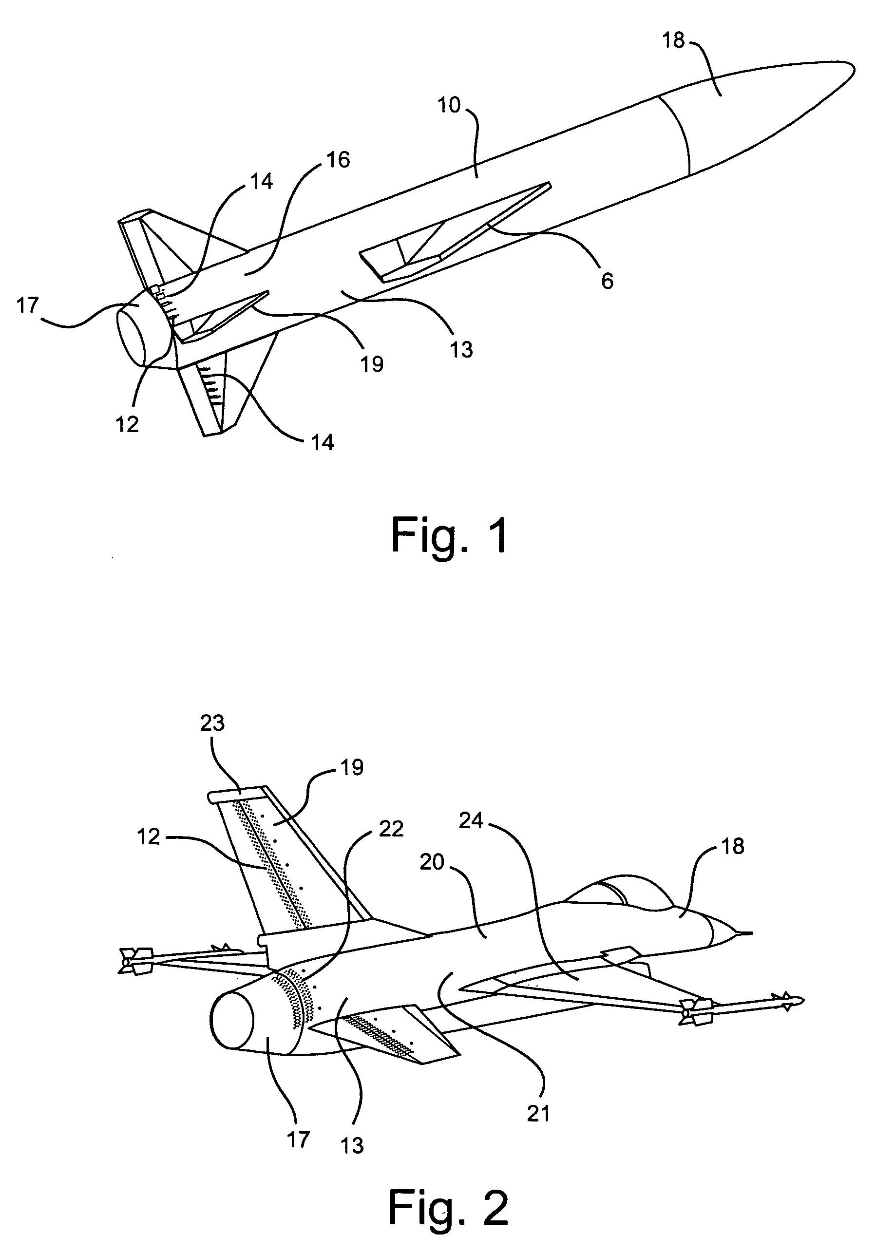
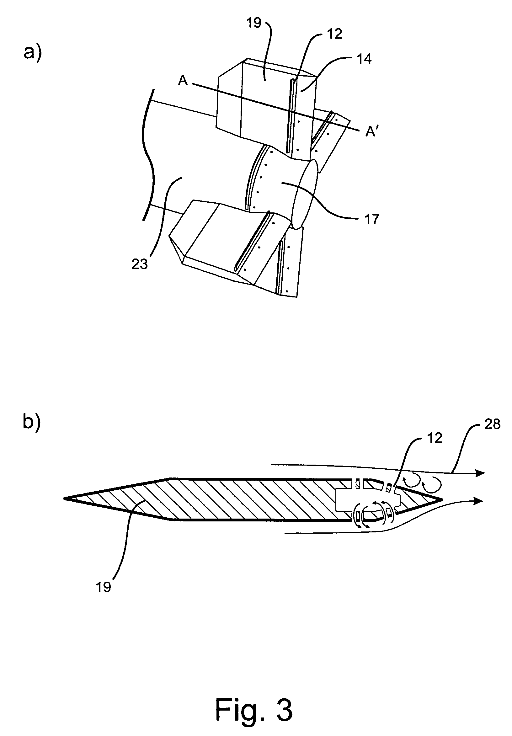
[0027]The present invention relates to an aerodynamic flow control system and more particularly to aircraft or missile with an afterbody flow control system for enhanced maneuverability and stabilization. The afterbody of the missile or aircraft for the present invention is defined as the back half of the length of the missile or aircraft, and more particularly as that section of fuselage behind the wings including but not limited to the tail section, i.e., the boattail and tail fins. The boattail is the rear portion of a missile or aircraft having decreasing cross-sectional area towards the rear. Preferably, the afterbody is the back 25% of the length of the missile or aircraft, and most preferably the afterbody is the tail section of the missile or aircraft.

[0028]The present invention most preferably relies on a successful marriage of the boattail geometry with the activatable flow effectors or active flow control devices incorporated within the geometry for aerodynamic control. T...


PUM


Abstract

The present invention relates to an afterbody flow control system and more particularly to aircraft or missile flow control system for enhanced maneuverability and stabilization. The present invention further relates to a method of operating the flow control system.
In one embodiment, the present invention includes a missile or aircraft comprising an afterbody and a forebody; at least one activatable flow effector on the missile or aircraft afterbody; at least one sensor each having a signal, the at least one sensor being positioned to detect forces or flow conditions on the missile or aircraft afterbody; and a closed loop control system; wherein the closed loop control system is used for activating and deactivating the at least one activatable flow effector based on at least in part the signal of the at least one sensor.

Description

CROSS REFERENCE TO RELATED APPLICATIONS[0001]This application is a continuation-in-part of U.S. patent application Ser. No. 10 / 336,117 filed Jan. 3, 2003 now U.S. Pat. No. 6,685,143.[0002]The U.S. Government has a paid-up license in this invention and the right in limited circumstances to require the patent owner to license others on reasonable terms provided for by the terms of grant DAAE30-02-C-1052 awarded by the U.S. Army.BACKGROUND OF THE INVENTION[0003]1. Field of the Invention[0004]The present invention relates to an aerodynamic flow control system and more particularly to aircraft or missile afterbody flow control system for enhanced maneuverability and stabilization at low angles of attack. The present invention further relates to a method of operating the flow control system.[0005]2. Technical Background[0006]Traditional aircraft and missile maneuvering technologies utilize conventional control surfaces such as tail-fins and canards to provide control and stability through...

Claims


Application Information

Patent Timeline
IPC IPC(8): B64C21/00B64C5/12F42B10/14
CPCB64C5/12F42B10/14G05D1/0088F42B15/01F41G7/00F42B10/64G05D1/0816F42B10/60F42B10/62B64C23/06Y02T50/10B64C21/00F42B10/02
Inventor DICOCCO, JACKPRINCE, TROYPATELNG, TSUN MING TERRY
Owner ORBITAL RES
Why Eureka
Try Eureka