Automobile seat

a technology for automobiles and seats, applied in the direction of chairs, pedestrian/occupant safety arrangements, vehicular safety arrangements, etc., can solve the problems of insufficient deformation and injury to the seat occupant, and achieve the effects of preventing the neck of the seat occupant from being injured, simple construction, and large impact energy

Inactive Publication Date: 2006-07-04
DELTA KOGYO CO LTD
View PDF13 Cites 55 Cited by
  • Summary
  • Abstract
  • Description
  • Claims
  • Application Information

AI Technical Summary

Benefits of technology

[0009]It is accordingly an objective of the present invention to provide an automobile seat having a simple construction and exhibiting high safety that ensures an amount of deformation sufficient to absorb large impact energy.
[0017]According to the present invention, the insertion hole for the fastening member and the impact absorbing structure are formed in the side frame, and when a load greater than a predetermined value is inputted to the seat from behind, a lower portion of the seat back frame is pushed upon a rearward movement of a seat occupant to thereby cause the fastening member to move rearward while deforming the impact absorbing structure, thereby absorbing impact. Accordingly, a sufficient amount of deformation that can absorb large impact energy is ensured with a simple construction.
[0018]Because the seat back frame rotates relative to the side frame upon a rearward movement of the fastening member, the headrest mounted on the upper portion of the seat back moves forward, thereby making it possible to prevent a neck of the seat occupant from being injured.

Problems solved by technology

When a rear-end collision has occurred, an impact applied to an automobile body is transmitted to a human body via a seat and may injure an occupant of the seat.
The seat back frame structure as disclosed in the above-described patent publications is intended to absorb impact inputted from outside by deforming a portion of the seat back frame, but cannot ensure an amount of deformation sufficient to absorb large impact energy and, hence, there is still room for improvement.

Method used


Image

  • Automobile seat
  • Automobile seat
  • Automobile seat

Examples


embodiment 1

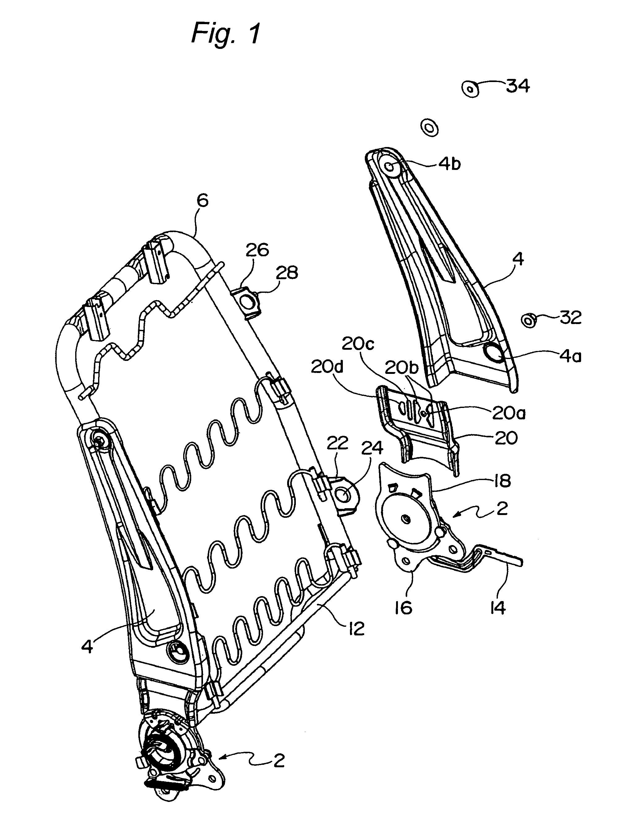
[0040]FIG. 1 depicts a seat back frame assembly of an automobile seat according to a first embodiment of the present invention, which is tiltably mounted on a seat cushion frame assembly (not shown). As shown therein, the seat back frame assembly includes a pair of side frames 4 mounted on the seat cushion frame assembly via respective recliner adjusters 2, and a seat back frame 6 mounted on the pair of side frames 4. A headrest 8 (see FIGS. 3A and 3B) is mounted on an upper portion of the seat back frame 6.

[0041]The recliner adjusters 2 are connected to each other via a connecting shaft 12. Operation of an operation lever 14 mounted on one of the recliner adjusters 2 allows the side frames 4 to be set to a desired angle.

[0042]Each of the recliner adjusters 2 includes a lower bracket 16 secured to the seat cushion frame assembly, and an upper bracket 18 rotatable relative to the lower bracket 16. Because the present invention does not focus on the recliner adjusters 2, detailed desc...

embodiment 2

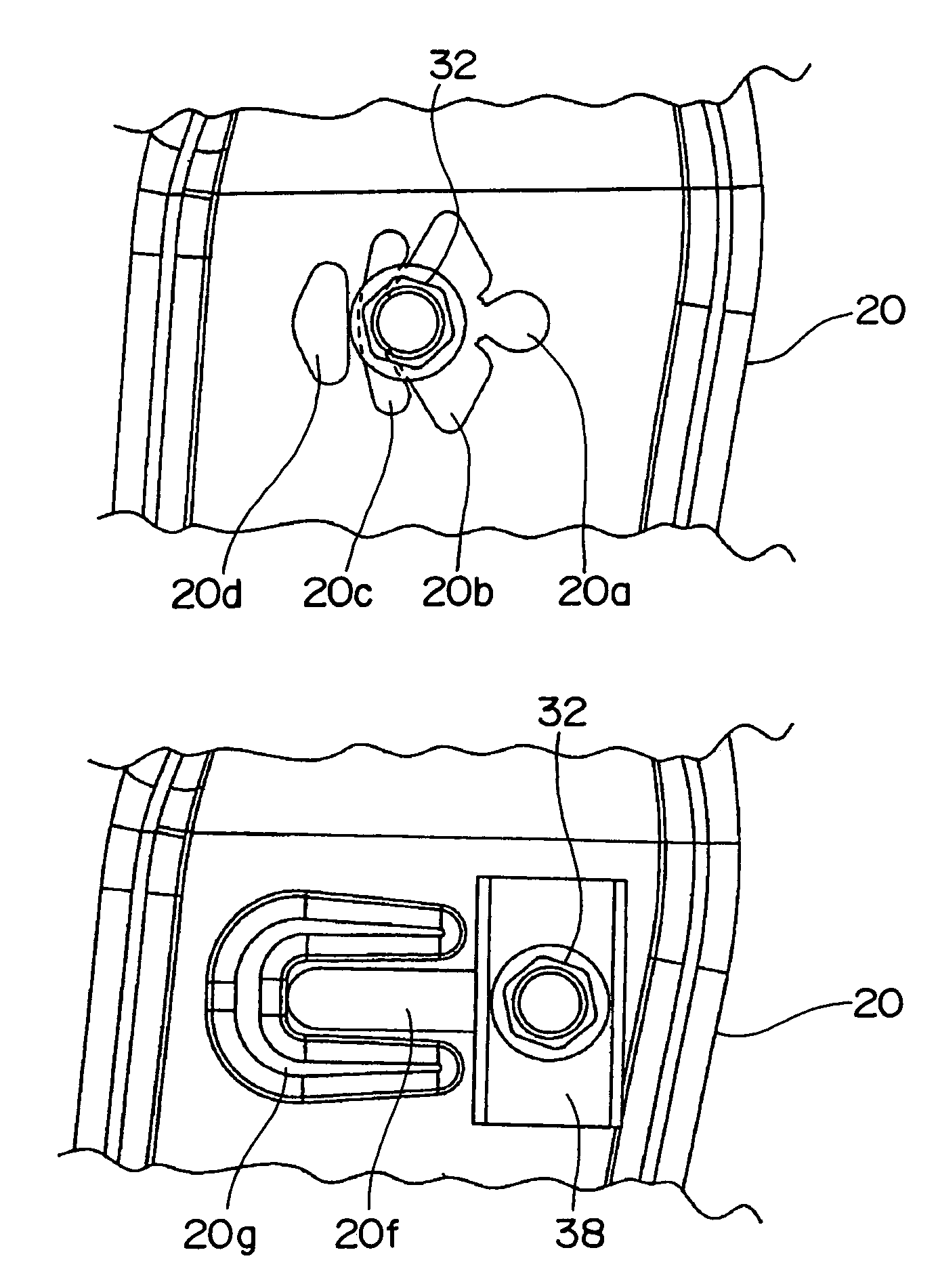
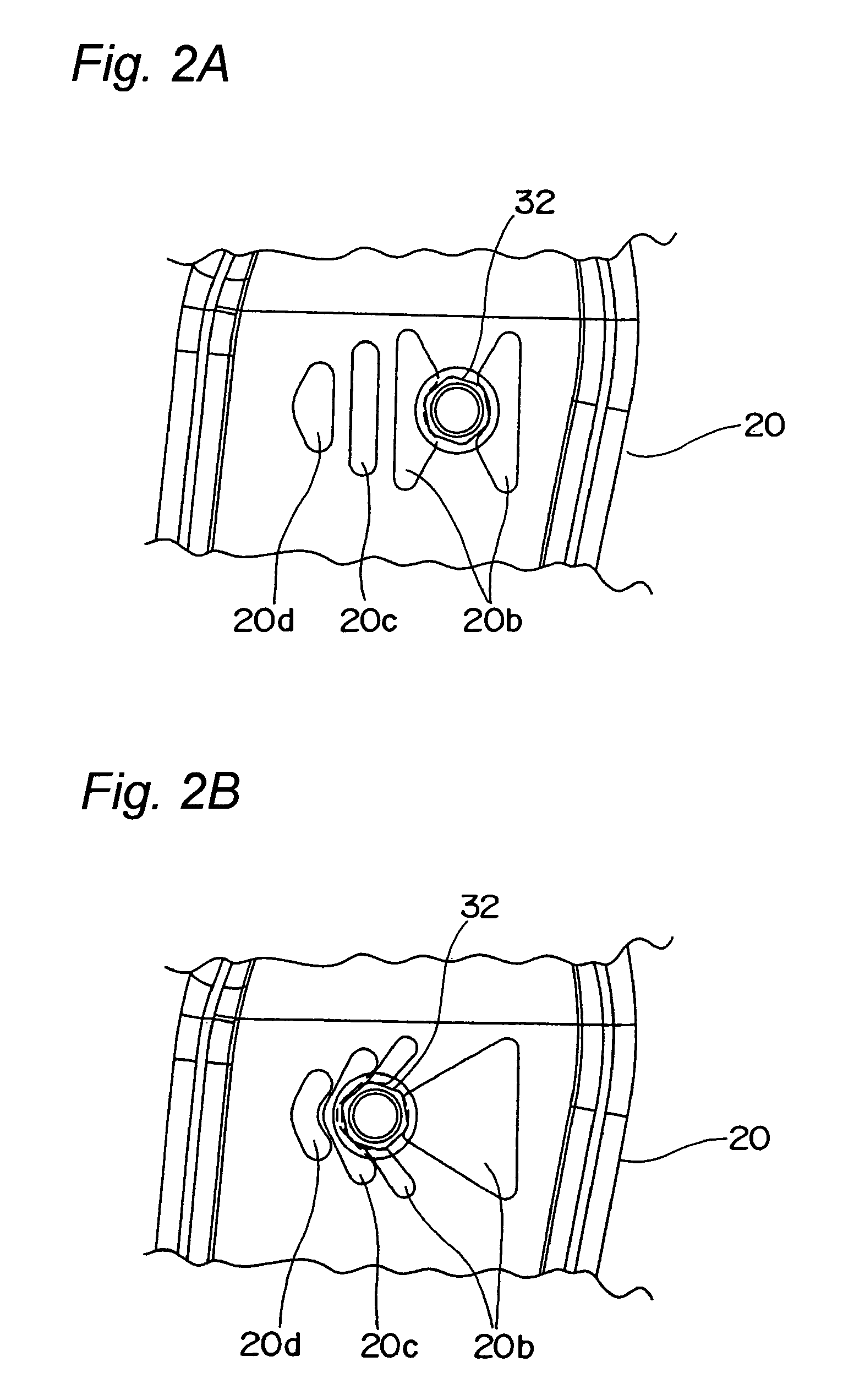
[0053]FIG. 4 and FIGS. 5A to 5C depict a seat back frame assembly of an automobile seat according to a second embodiment of the present invention. Of a pair of first impact absorbing holes 20b formed on respective sides of the bolt insertion hole 20a in the first embodiment referred to above, a front one of the first impact absorbing holes 20b is dispensed with in this embodiment.

[0054]By this construction, when a load greater than a predetermined value is inputted to the seat from behind in an event of, for example, a rear-end collision, a portion of inner side frame 20 that is positioned between the bolt insertion hole 20a and first impact absorbing hole 20b splits. Thereafter, first bolt 24 further moves rearward and deforms second impact absorbing hole 20c or both the second and third impact absorbing holes 20c, 20d to absorb an impact, as best shown in FIG. 5C. As is the case with the first embodiment, an amount of deformation depends on a magnitude of the impact, and the first...

embodiment 3

[0057]FIG. 6 and FIGS. 7A to 7C depict a seat back frame assembly of an automobile seat according to a third embodiment of the present invention.

[0058]As shown in these figures, inner side frame 20 has an elongated hole 20e defined therein rearwardly of bolt insertion hole 20a so as to extend generally horizontally and communicate with the bolt insertion hole 20a. A width of the elongated hole 20e is less than a diameter of first bolt 24 inserted into the bolt insertion hole 20a. A coned disc spring 36 is mounted on the first bolt 24 between the inner side frame 20 and first nut 32.

[0059]Because the width of the elongated hole 20e is set to be less than the diameter of the first bolt 24, when a load greater than a predetermined value is inputted to the seat from behind in an event of, for example, a rear-end collision, the first bolt 24 moves rearward while widening the elongated hole 20e behind it, as best shown in FIG. 7C, and an impact is absorbed by deformation of the elongated ...


PUM


Abstract

An automobile seat includes a seat cushion and a seat back tiltably mounted on the seat cushion. The automobile seat also includes a seat cushion frame, a side frame mounted on the seat cushion frame, a seat back frame mounted on the side frame so as to be rotatable within a limited angle, and a fastening member mounted on the seat back frame. The side frame has an insertion hole defined therein in which the fastening member is inserted and also has an impact absorbing structure. When a load greater than a predetermined value is inputted to the seat from behind, a lower portion of the seat back frame is pushed upon a rearward movement of a seat occupant to thereby cause the fastening member to move rearward while deforming the impact absorbing structure. As a result, the seat back frame rotates with respect to the side frame, and an impact is absorbed by deformation of the impact absorbing structure.

Description

BACKGROUND OF THE INVENTION[0001]1. Field of the Invention[0002]The present invention relates to an automobile seat capable of easing, when an automotive vehicle has come into a rear-end collision, an impact to a lumbar part of a seat occupant.[0003]2. Description of the Related Art[0004]When a rear-end collision has occurred, an impact applied to an automobile body is transmitted to a human body via a seat and may injure an occupant of the seat.[0005]Japanese Laid-Open Patent Publication No. 2000-118279 discloses a seat back frame structure for an automobile seat wherein a horizontal frame having a generally L-shaped cross section extends between lower end portions of opposite side frames. In this seat back frame structure, a plurality of horizontally extending stiffening beads or ridges are formed on a bottom wall and a vertical wall of the horizontal frame, while two vertically extending energy absorbing beads or ridges are formed on the vertical wall of the horizontal frame. The...

Claims


Application Information

Patent Timeline
Patent Type & Authority Patents(United States)
IPC IPC(8): B60N2/42B60N2/427B60R21/00B60R21/02B60R21/055
CPCB60N2/4228B60N2/682B60N2/42745B60N2/42709
Inventor KAWASHIMA, YOSHIHITO
Owner DELTA KOGYO CO LTD
Why Eureka
Try Eureka