Microchip drug delivery devices

a drug delivery and microchip technology, applied in the direction of transportation and packaging, other medical devices, electrolysis components, etc., can solve the problems of drug delivery, patients often forget, are unwilling or unable to take their medication, and drug delivery becomes problemati

Inactive Publication Date: 2006-07-04
MASSACHUSETTS INST OF TECH
View PDF113 Cites 104 Cited by
  • Summary
  • Abstract
  • Description
  • Claims
  • Application Information

AI Technical Summary

Problems solved by technology

This makes the selection of a proper drug delivery method problematic.
Patients often forget, are unwilling, or are unable to take their medication.
Drug delivery also becomes problematic when the drugs are too potent for systemic delivery.
However, these devices are relatively simple.
These are complicated and subject to breakdown.
Moreover, due to complexity and size restrictions, they are unsuitable to deliver more than a few drugs or drug mixtures at a time.

Method used


Image

  • Microchip drug delivery devices
  • Microchip drug delivery devices
  • Microchip drug delivery devices

Examples


example 1

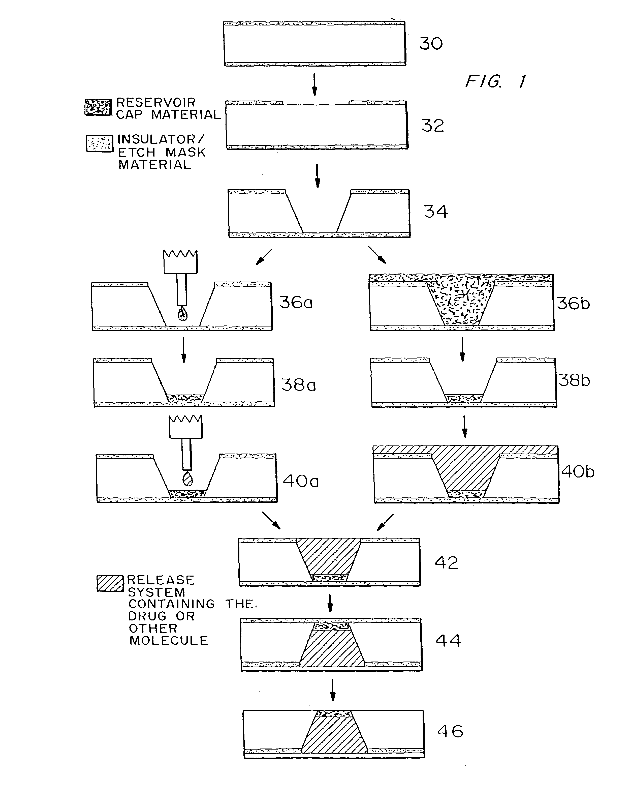
Fabrication of Active Release Microchip

1) Obtain double side polished, prime grade, (100) oriented silicon wafers.

[0075]Wafer thickness=approximately 295–310 μm

2) Deposit approximately 1600–1900 Å of low stress (10:1, silicon rich) silicon nitride on both sides of the wafers in an SVG / Thermco 7000 Series vertical tube reactor (VTR).

[0076]Gas Flows: Ammonia (NH3)=24 sccm[0077]Dichlorosilane (SiH2Cl2)=253 sccm

[0078]Temperature=780° C.

[0079]Chamber Pressure=268 mtorr

[0080]Deposition Rate=approximately 30 Å / min.

3) Pattern positive photoresist (PR) as squares (approximately 500 μm by 500 μm) serving as the large reservoir openings on one side of the wafers having low stress silicon nitride deposited on them.

[0081]Hexamethyldisilazane deposition on both sides of the wafer[0082](“HMDS vapor prime”) in vacuum oven[0083]approximately 30 min. at 150° C.

[0084]Photoresist (PR) Type—OCG825-20

[0085]PR Spin Speed and Times (for a Solitec Inc. Model 5110 spinner)[0086]7 sec. at 500 rpm (coat)[0087]...

example 2

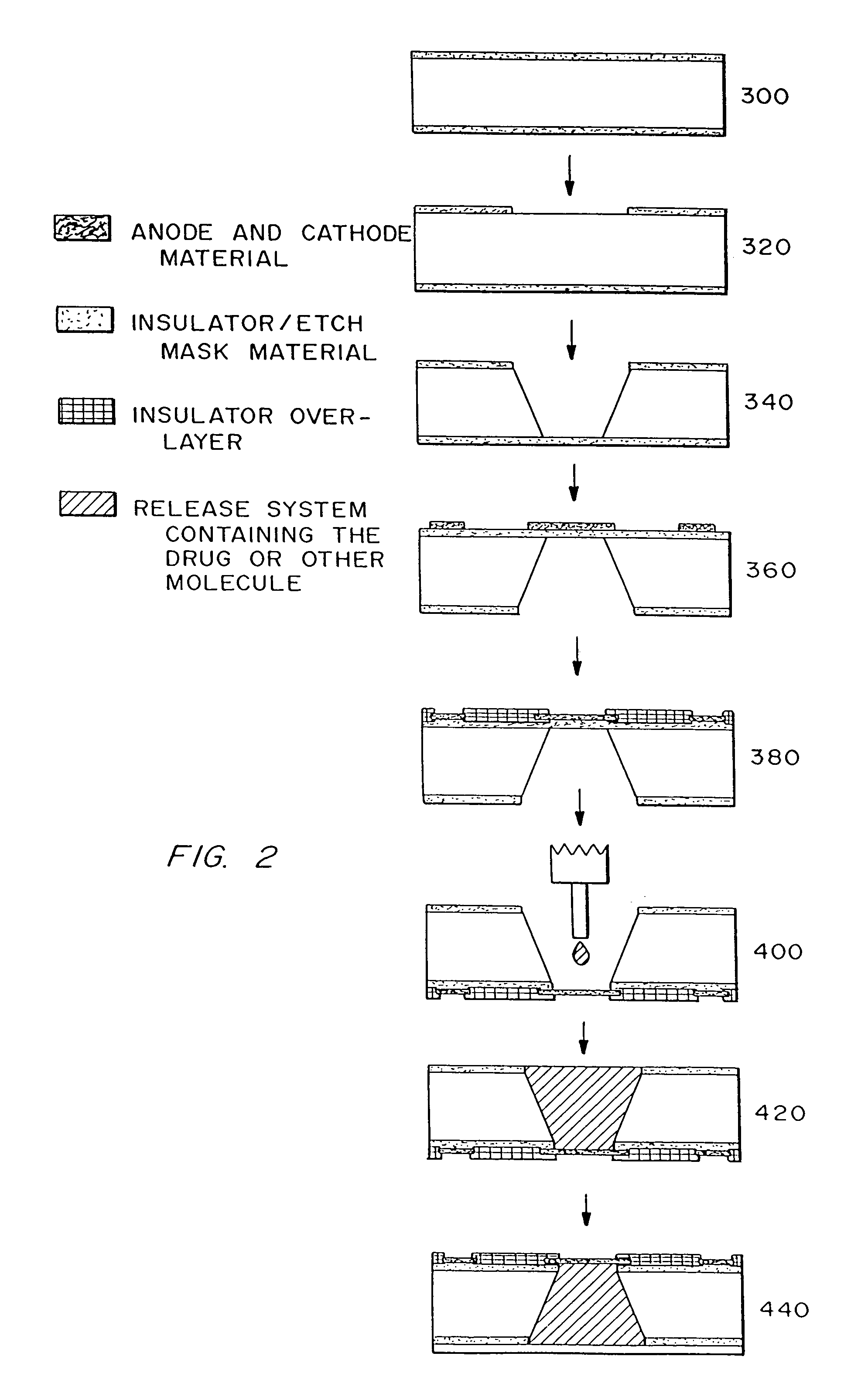
Fabrication of Passive Release Microchip

[0181]1) Obtain double side polished, prime grade, (100) oriented silicon wafers for devices having reservoirs extending completely through the wafer or single side polished, prime grade, (100) oriented silicon wafers for devices having reservoirs that do not extend completely through the wafer.

[0182]Wafer thickness=approximately 295–310 μm for devices with reservoirs extending completely through the wafer (devices that do not have reservoirs extending all the way through the wafer can be of any desired thickness)

2) Deposit approximately 1600–1900 Å of low stress (10:1, silicon rich) silicon nitride on both sides of the wafers in an SVG / Thermco 7000 Series vertical tube reactor (VTR).

[0183]Gas Flows: Ammonia (NH3)=24 sccm[0184]Dichlorosilane (SiH2Cl2)=253 sccm

[0185]Temperature=780° C.

[0186]Chamber Pressure=268 mtorr

[0187]Deposition Rate=approximately 30 Å / min.

[0188]3) Pattern positive PR as squares (approximately 500 μm by 500 μm for devices w...

example 3

Microchip with Passive Timed Drug Release

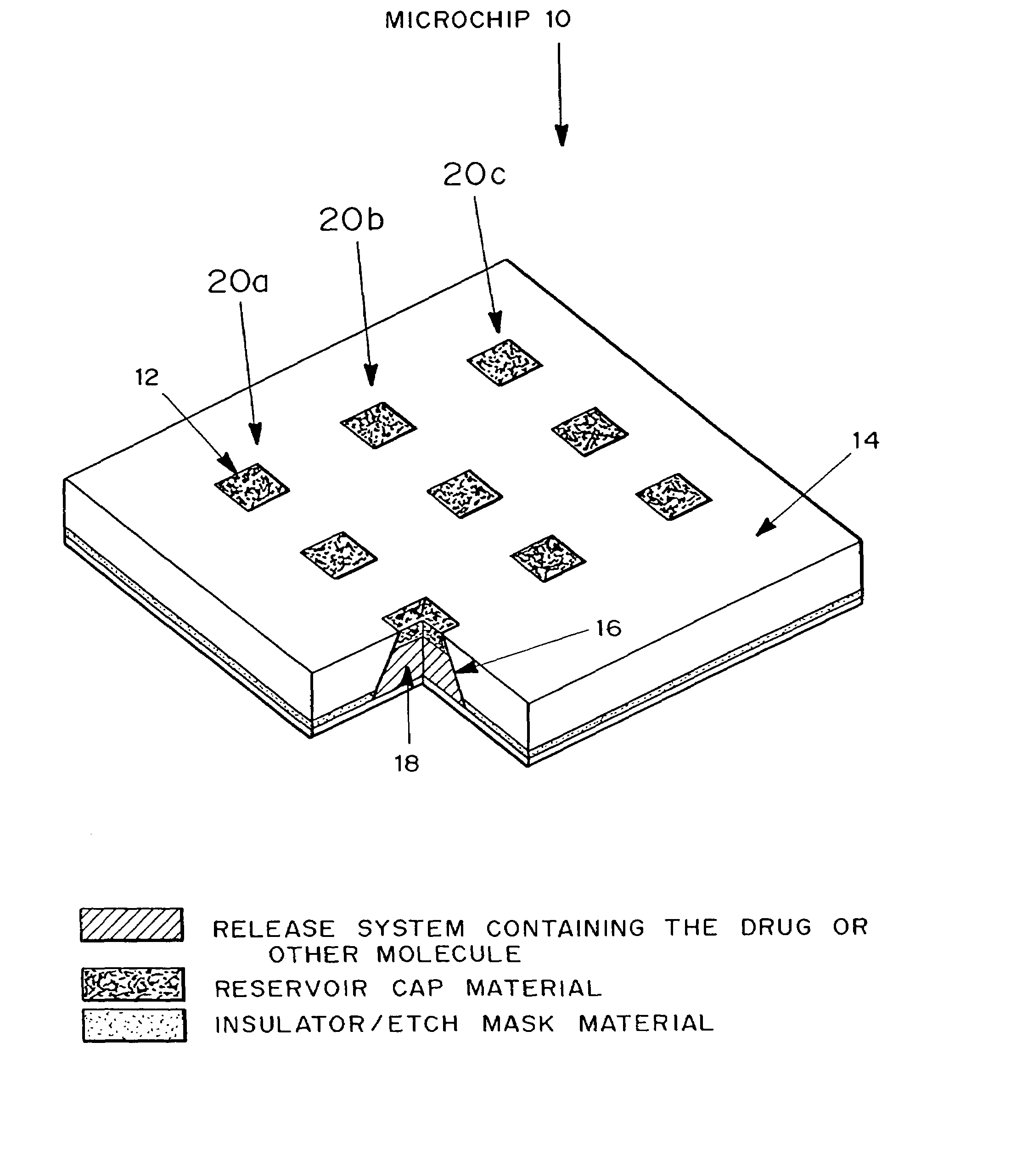
[0240]A passive timed release device, microchip 10 is shown in FIG. 4. Microchip 10 is formed from substrate 14. Reservoirs 16 are etched into substrate 14. Positioned in reservoirs 16 is a release system containing molecules for delivery 18. The reservoirs are capped with reservoir caps 12. The release system and the molecules for delivery 18 can vary between rows 20a, 20b, 20c, and within reservoirs of each row.

[0241]Microchip 10 can be inserted into solution for in vitro applications or be implanted in a selected part of the body for in vivo applications and left to operate without requiring further attention. When exposed to the surrounding fluids, reservoir caps 12 will degrade or become permeable to the release system containing molecules for delivery 18.


PUM

PropertyMeasurementUnit
thicknessaaaaaaaaaa
thicknessaaaaaaaaaa
thickaaaaaaaaaa

Abstract

Devices are provided for the controlled release of drug or other molecules. The devices include (1) a substrate, which optionally includes two or more substrate portions bonded together, (2) at least two reservoirs in the substrate, (3) a release system disposed in the reservoirs that includes the molecules for release and optionally a matrix material, and (4) active or passive means for controlling release of the molecules from the reservoirs. In one embodiment, a reservoir cap is positioned on, or within a portion of, the reservoir and over the molecules, so that the molecules are controllably released from the device by diffusion through or upon disintegration of the reservoir cap.

Description

CROSS-REFERENCE TO RELATED APPLICATIONS[0001]This is a continuation-in-part of application Ser. No. 09 / 022,322, filed Feb. 11, 1998, now U.S. Pat. No. 6,123,861, which is a continuation-in-part of application Ser. No. 08 / 675,375, filed Jul. 2, 1996, now U.S. Pat. No. 5,797,898.BACKGROUND OF THE INVENTION[0002]This invention relates to miniaturized drug delivery devices and more particularly, to controlled time and rate release multi-welled drug delivery devices.[0003]Drug delivery is an important aspect of medical treatment. The efficacy of many drugs is directly related to the way in which they are administered. Some therapies require that the drug be repeatedly administered to the patient over a long period of time. This makes the selection of a proper drug delivery method problematic. Patients often forget, are unwilling, or are unable to take their medication. Drug delivery also becomes problematic when the drugs are too potent for systemic delivery. Therefore, attempts have bee...

Claims


Application Information

Patent Timeline
Patent Type & Authority Patents(United States)
IPC IPC(8): A61K9/22A61K9/00A61M37/00
CPCA61K9/0009A61K9/0024A61K9/0097C25F7/00C25F5/00A61M37/00A61M2205/0244A61M5/14276Y10T137/8242
Inventor SANTINI, JR., JOHN T.CIMA, MICHAEL J.LANGER, ROBERT S.
Owner MASSACHUSETTS INST OF TECH
Why Eureka
Try Eureka