Electrode arrangement for generating functional field barriers in microsystems

a technology of functional field barriers and electrodes, which is applied in the direction of electrostatic separators, diaphragms, electrolysis, etc., can solve the problems of limited ability to generate force gradients within the channel structure, the effect of generating polarisation forces, and the stability and longevity of microelectrodes

Inactive Publication Date: 2006-07-04
EVOTEC TECH GMBH +1
View PDF20 Cites 22 Cited by
  • Summary
  • Abstract
  • Description
  • Claims
  • Application Information

AI Technical Summary

Benefits of technology

[0007]It is the object of the invention to provide improved micro systems for dielectrophoretic particle deflection, with said arrangements being suitable to overcome the disadvantages of conventional microsystems, and in particular providing enlarged applications and making it possible to generate field barriers which are also effective in covering shorter channel sections. Furthermore it is the object of the invention to provide novel applications for such microsystems.
[0010]It is thus a subject of the invention, to optimise microelectrodes in relation to their effect on suspended particles which may comprise natural or synthetic particles, e.g. for generating maximum forces while at the same time causing minimum electrical losses.
[0011]The invention provides the following advantages. The design of the microelectrodes can e.g. be adapted to the flow profile in the suspension liquid. This provides the advantage that the microelectrodes can be shorter and can be designed for generating lesser barriers while being equally as effective as conventional microelectrodes in the shape of straight bands. This has an advantageous effect on the lifetime and function of the microelectrodes and thus of the entire microsystems. Moreover the space available in a microsystem can be used more effectively. Furthermore, electrode arrangements are provided with which gradients can be generated, and thus depending on the respective channel region, forces of various strength can be generated. It is for example provided for the field barriers of the microelectrodes to be designed such that larger polarisation forces act upon the particles in the middle of the channel when compared to the particles at the edge of the channel.
[0012]The creation of field barriers according to the invention along curved reference surfaces also makes it possible to create novel applications of microsystems, in particular for guiding suspended particles into particular channel regions, for sorting suspended particles according to their passive electrical properties or for collecting or retaining suspended particles in particular channel sections. For this latter application, the microelectrodes are designed so as to comprise a geometric shape for retaining particles in a solution flow or for generating a particle formation. All the applications mentioned provide contactless manipulation of the suspended particles vis-a-vis the microsystem, a feature which is significant in particular for manipulating biological cells or cell components.

Problems solved by technology

Conventional microsystems have disadvantages in relation to the effectiveness of generating polarisation forces; the stability and longevity of the microelectrodes; and a limited ability of generating force gradients within the channel structure.
These disadvantages are in particular linked to the electrode bands which are formed along comparatively long lengths in the channel.
However, long electrode bands are also more susceptible to malfunction.
Faults in workmanship or mechanical loads can cause interruptions which lead to electrode failure.
Due to the disadvantages mentioned, the application of said fluidic microsystems with dielectrophoretic particle manipulation has been limited to guiding the particles in the channel structure or to deflecting particles from a given flow.

Method used


Image

  • Electrode arrangement for generating functional field barriers in microsystems
  • Electrode arrangement for generating functional field barriers in microsystems
  • Electrode arrangement for generating functional field barriers in microsystems

Examples


Embodiment Construction

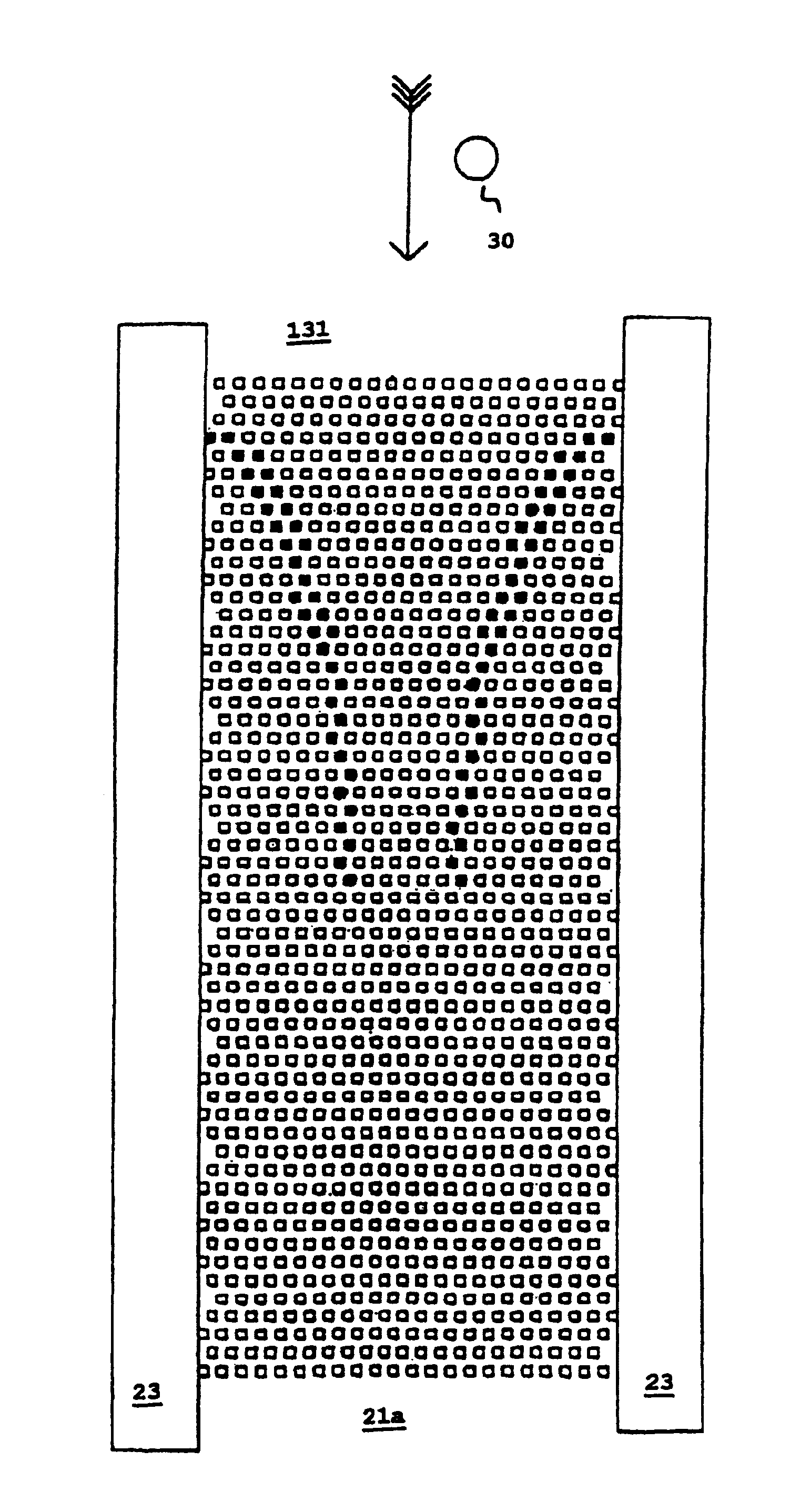
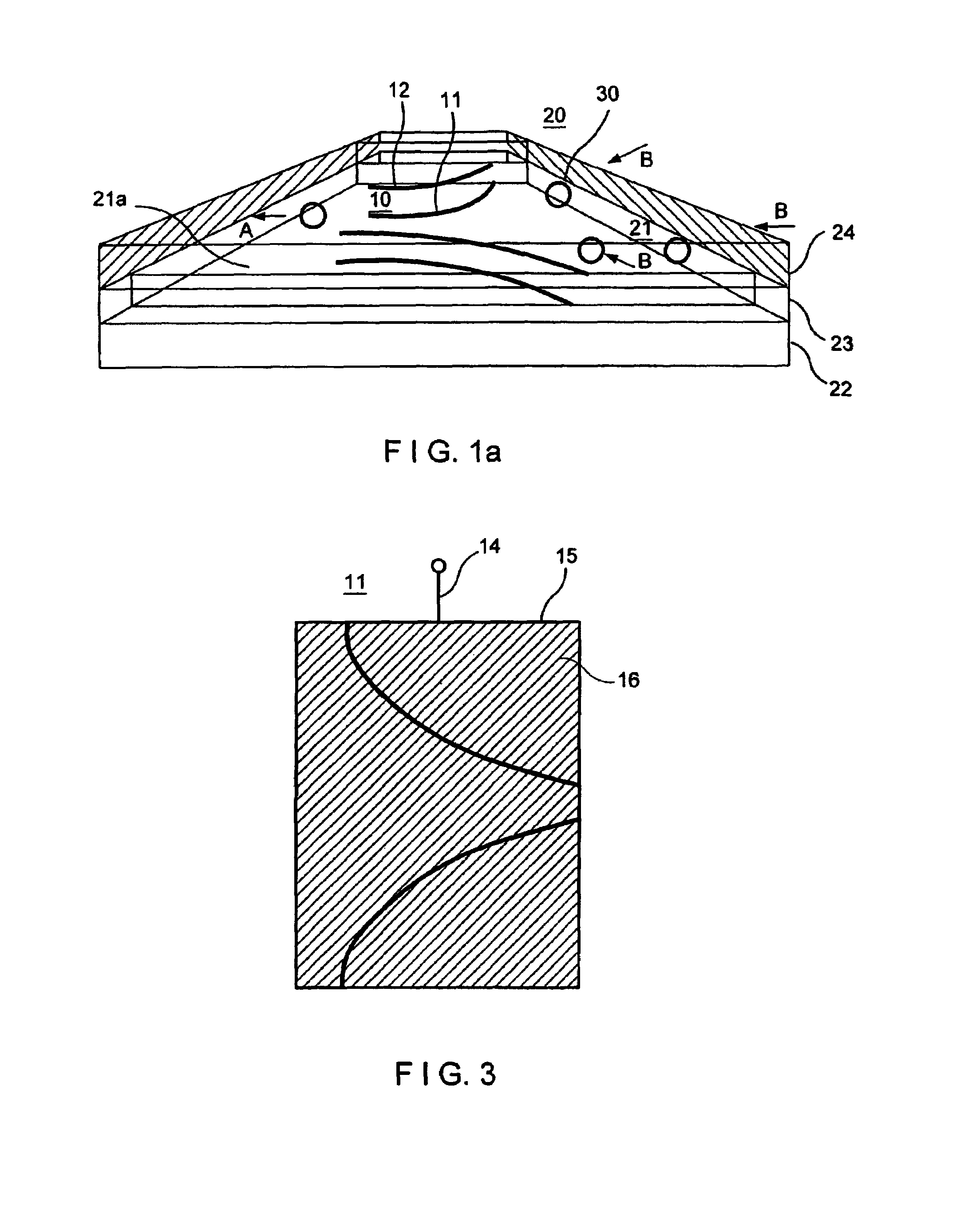
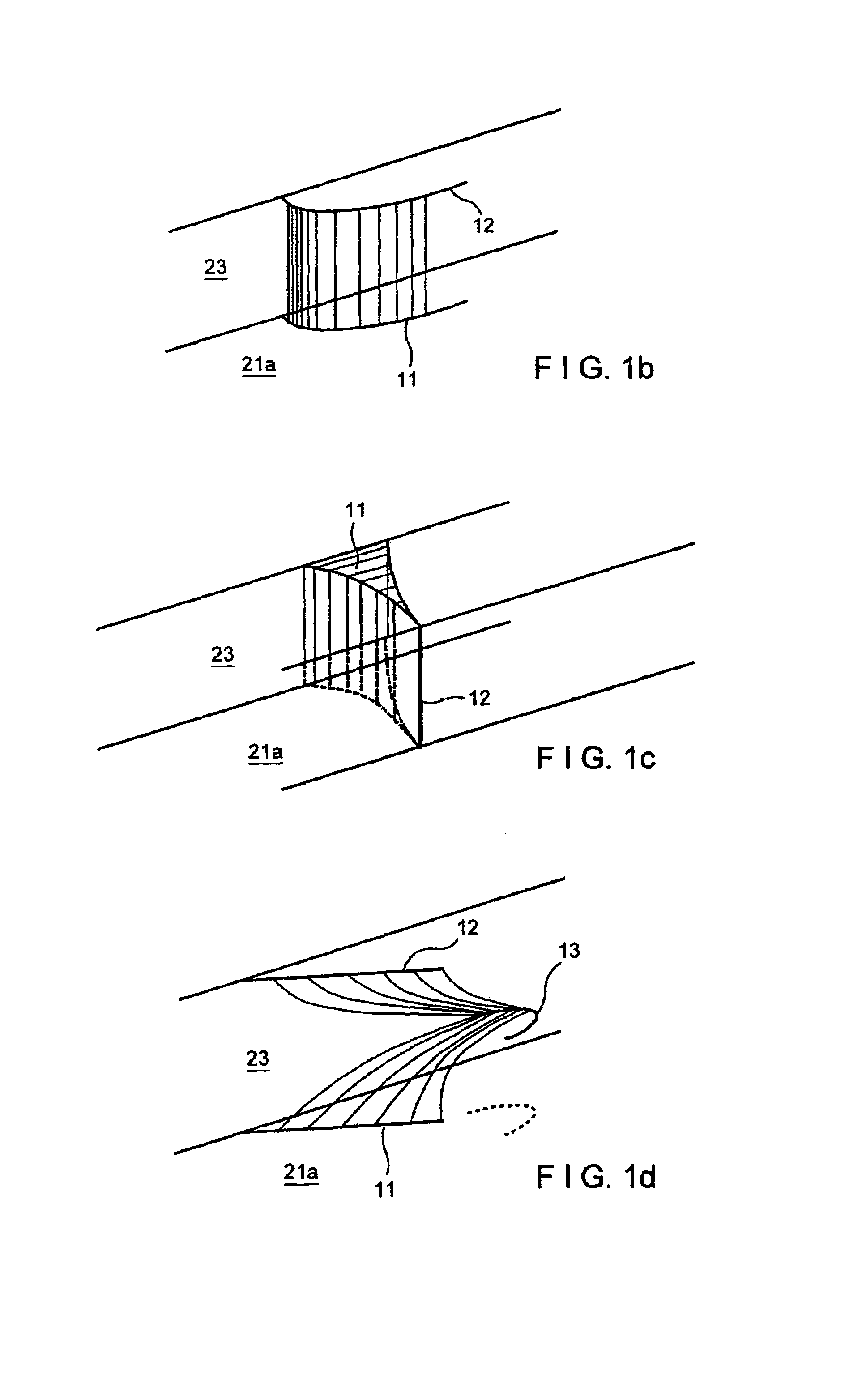
[0026]FIG. 1a diagrammatically shows an example of an embodiment of microelectrodes for generating field barriers in microchannels. The fluidic microsystem 20 is shown in sections in distorted perspective lateral view of a channel structure. The channel 21 is formed by two spacers 23 arranged at a distance on a substrate 22, spacers 23 supporting a cover part 24. The width and height of the channel is approx. 200 pm and 40 pm respectively but they can also be less. Such structures are for example made using process techniques of semiconductor technology which are known per see The substrate 22 forms the bottom surface 21a of the channel 21. Accordingly the cover surface (for reasons of clarity not specially emphasised) is formed by the cover part 24. The electrode arrangement 10 comprises microelectrodes 11, 12 attached to the bottom surface 21a or the cover surface. Each of the microelectrodes 11, 12 comprises curved electrode bands which are described in more detail below.

[0027]In...


PUM

PropertyMeasurementUnit
lengthaaaaaaaaaa
thicknessaaaaaaaaaa
widthaaaaaaaaaa

Abstract

A microsystem adapted for dielectrophoretic manipulation of particles in a suspension liquid wherein the microsystem has a channel with channel walls and a longitudinal extension. An electrode arrangement is present which has at least one microelectrode on at least one of the channel walls. This acts to generate a field barrier which crosses the channel at least partly. The microelectrode has a band-shape or has a multitude of straight electrode sections connected to each other. The band-shape has a predetermined curvature or the straight electrode sections are arranged with predetermined different angles so that the field barrier has a predetermined curvature relative to the longitudinal extension of the channel.

Description

[0001]This application is a 371 of PCT / EP99 / 04470, filed Jun. 28, 1999.[0002]The invention relates to electrode arrangements for generating functional field barriers in microsystems adapted for manipulation of suspended particles, in particular functional microelectrodes for dielectrophoretic deflection of microscopic particles, and microsystems equipped with such electrode arrangements as well as their applications.BACKGROUND OF THE INVENTION[0003]Manipulation of suspended particles in fluidic microsystems is generally known and has for example been described by G. Fuhr et al in “Naturwissenschaften”, vol. 81, 1994, p. 528 ff. The microsystems form in particular channel structures through which a suspension fluid flows with the particles to be manipulated. As a rule the cross-sectional area of these channel structures is rectangular, with the width of the channel walls, which in operating position form the top and bottom (bottom / cover surfaces), being greater than the lateral chann...

Claims


Application Information

Patent Timeline
Patent Type & Authority Patents(United States)
IPC IPC(8): G01N27/447G01N27/453B01F13/00B01L3/00B03C5/00B03C5/02C12M1/42G01N15/04
CPCB01F13/0076B01F13/0077B01L3/502761B03C5/026B01L3/502746B01L2200/0647B01L2200/0668B01L2300/0816B01L2300/0864B01L2400/0409B01L2400/0415B01L2200/0652C12M47/04C12M33/00B01F33/3032B01F33/3031
Inventor FUHR, GUNTERSCHNELLE, THOMASHAGEDORN, ROLFMULLER, TORSTEN
Owner EVOTEC TECH GMBH
Why Eureka
Try Eureka