
Thermal recording material

a recording material and recording technology, applied in thermography, duplicating/marking methods, instruments, etc., can solve the problems of unfavorable maintenance of portable printers, inability to permit, and unclear printing,

Inactive Publication Date: 2006-07-04
MITSUBISHI PAPER MILLS LTD
View PDF20 Cites 0 Cited by
  • Summary
  • Abstract
  • Description
  • Claims
  • Application Information

AI Technical Summary

Benefits of technology

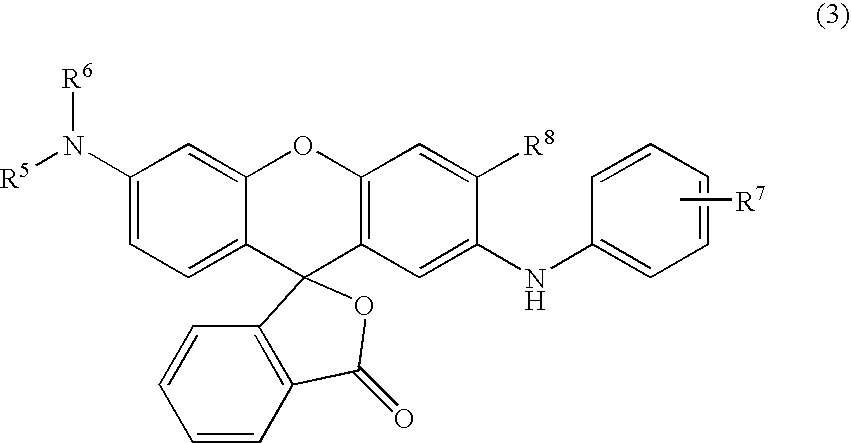
The present invention provides a thermal recording material with high thermal response and color density, excellent image retainability, and reduced residue adhesion to the thermal printer. The material contains a thermal recording layer with a diphenylsulfone derivative, an amide derivative, and a fluorane derivative. The weight ratio of the diphenylsulfone derivative to the amide derivative is important and can affect the properties of the material. Other sensitizers can also be added to the material to improve its performance. The thermal recording layer may also contain a compound of the general formula (4), (5), or (7) described above. Overall, the invention provides a thermal recording material with improved performance and reduced residue adhesion to the thermal printer.

Problems solved by technology

That is, in the above thermal recording material for use as an accounting-related recording sheet, an unclear printing caused by residues adhering to a thermal head or the like during a long-distance printing cannot be permitted.
This is true to a higher degree with regard to a portable printer using a sheet for the above bills, since it is difficult to have the portable printer checked for maintenance, for example, to have a thermal head cleaned, when a meter checker is outside.
Under the circumstances, however, no thermal recording materials that cause fewer residues to adhere to a thermal head have been provided even if the above methods are employed, and it is still demanded to improve the above property on the basis of a thermal recording layer alone for decreasing energy and a cost.
Since, however, the addition of these sensitizers involves an increase in the amount of a heat-fusible substance, it is very difficult to decrease the amount of residues adhering to a thermal head.

Method used


Image

  • Thermal recording material
  • Thermal recording material
  • Thermal recording material

Examples


example 1

(1) Preparation of Heat-Sensitive Coating Liquid

[0132]Various dispersions prepared above, other dispersions and an aqueous solution were mixed in the following amount ratios, and water was added such that a coating liquid had a concentration of 15%. The mixture was fully stirred to give a heat-sensitive coating liquid.

[0133]

Dispersion A 60 partsDispersion C 30 partsDispersion E 60 partsDispersion P100 parts40% Zinc stearate aqueous solution 25 parts10% Polyvinyl alcohol aqueous solution272 partsWater300 parts

(2) Preparation of Heat-Sensitive Coated Paper

[0134]A coating liquid having the following composition was coated on a woodfree paper having a basis weight of 40 g / m2 to form a coating having a solid application amount of 9 g / m2, and the coating was dried to give a coated paper for heat-sensitive coating.

[0135]

Calcined kaolin100 parts50% Styrene-butadiene latex aqueous dispersion 24 partsWater200 parts

(3) Preparation of Thermal Recording Material

[0136]The heat-sensitive coating l...

example 2

[0137]A thermal recording material was obtained in the same manner as in Example 1 except that the amount of Dispersion E was changed from 60 parts to 120 parts.

example 3

[0138]A thermal recording material was obtained in the same manner as in Example 1 except that the amount of Dispersion E was changed from 60 parts to 240 parts.


PUM

PropertyMeasurementUnit
melting pointaaaaaaaaaa
particle diameteraaaaaaaaaa

Abstract

Provided is a thermal recording material that is excellent in thermal response and retainability of an image portion and which generates fewer residues adhering to the thermal head of a thermal printer.The thermal recording material having a thermal recording layer comprising a generally colorless or light-colored electron-donating dye precursor and an electron-accepting developer that reacts under heat to cause said dye precursor to form a color, said thermal recording layer containing a specific diphenylsulfone derivative, a specific amide derivative and a specific fluorane derivative, wherein the weight ratio of the specific diphenylsulfone derivative above and the specific amide derivative above is 2 / 1 to 1 / 2.

Description

[0001]This application is a U.S. national stage of International Application No. PCT / JP01 / 08592 filed Sep. 28, 2001.TECHNICAL FIELD[0002]The present invention relates to a thermal recording material, particularly to a thermal recording material that is excellent in thermal response and image retainability and which generates fewer residues adhering to the thermal head of a thermal printer so that it is free of a printing problem in long-distance printing.TECHNICAL BACKGROUND[0003]Generally, a thermal recording material has a substrate and a heat-sensitive recording layer formed thereon, the heat-sensitive recording layer containing, as main components, a generally colorless or light-colored electron-donating dye precursor and an electron-accepting developer that reacts under heat to cause the dye precursor to develop a color. When the thermal recording material is heated with a thermal head, a hot pen or a laser beam, the dye precursor and the electron-accepting developer readily re...

Claims


Application Information

Patent Timeline
Patent Type & Authority Patents(United States)
IPC IPC(8): B41M5/30B41M5/327B41M5/333B41M5/337
CPCB41M5/3275B41M5/3375B41M5/3336
Inventor HIZATATE, SHOJI
Owner MITSUBISHI PAPER MILLS LTD
Learn More