Check patentability & draft patents in minutes with Patsnap Eureka AI!

Autofocus system and microscope

a technology of autofocus and microscope, which is applied in the field of autofocus system and microscope, can solve the problem of taking a considerable amount of time to execute the focal adjustment, and achieve the effect of high degree of reliability

Active Publication Date: 2006-07-04
NIKON CORP
View PDF9 Cites 57 Cited by
  • Summary
  • Abstract
  • Description
  • Claims
  • Application Information

AI Technical Summary

Benefits of technology

[0009]The present invention provides an autofocus system capable of adjusting any point in a specimen to the focal point of an objective lens with a high degree of reliability.

Problems solved by technology

However, there is a problem with image contrast type autofocus systems in that the contrast of the image of a specimen with a pale color cannot be extracted quickly and thus it takes a considerable length of time to execute the focal adjustment.

Method used


Image

  • Autofocus system and microscope
  • Autofocus system and microscope
  • Autofocus system and microscope

Examples


Embodiment Construction

[0031]An embodiment of the present invention is now explained in reference to the drawings.

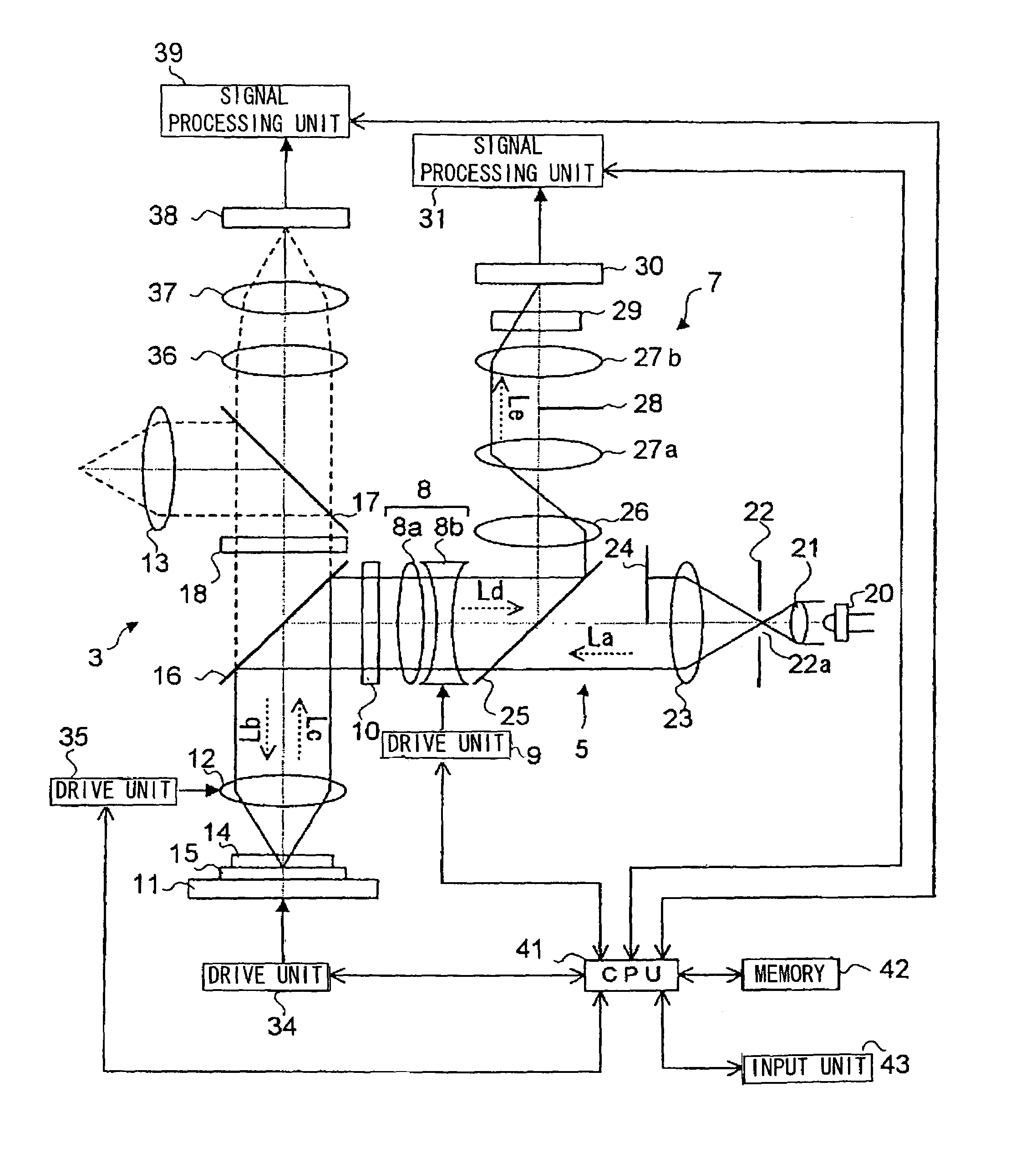
[0032]The autofocus system achieved in the embodiment of the present invention executes a focal adjustment through slit projection. A slit projection-type autofocus system irradiates slit illumination light onto a specimen and positions the specimen at the focal point of an objective lens by using reflected light from the specimen. The following is a brief explanation of the focal adjustment achieved in the slit projection-type autofocus system.

[0033]Slit illumination light is generated by passing light emitted from an auxiliary light source such as a light emitting diode (LED) through a slit. The slit illumination light is divided into two separate beams along the central line extending in the lengthwise direction. One of the illumination light beams is blocked, whereas the other illumination light beam is condensed through the objective lens and is irradiated onto an observation target objec...


PUM


Abstract

An autofocus system according to the present invention comprises: a light source; a focusing illumination optical system that forms an optical image generated with light from the light source on a target object through an objective lens; a focusing image forming optical system that receives through the objective lens reflected light generated as the optical image is reflected off the target object and forms a reflected image of the optical image; a photoelectric converter that is provided at an image forming position at which the reflected image is formed by the focusing image forming optical system to detect the reflected image; a signal output device that outputs a signal for controlling a focus actuator based upon a signal corresponding to the reflected image obtained at the photoelectric converter; and an image forming position adjustment device that adjusts an offset quantity between a focus position of the objective lens and an image forming position of the optical image by moving at least one of the image forming position of the optical image and the image forming position of the reflected image along an optical axis.

Description

INCORPORATION BY REFERENCE[0001]The disclosures of the following priority applications are herein incorporated by reference:[0002]Japanese Patent Application No. 2002-174877 filed Jun. 14, 2002[0003]Japanese Patent Application No. 2003-087278 filed Mar. 27, 2003BACKGROUND OF THE INVENTION[0004]1. Field of the Invention[0005]The present invention relates to a technology to be adopted when implementing autofocus control in a microscope.[0006]2. Description of the Related Art[0007]Autofocus systems adopted in conjunction with microscopes in the known art include image contrast type autofocus systems. When observing a biological specimen in a fluid under fluorescent light with an optical microscope (a biological microscope), such an autofocus system detects the contrast of the fluorescent image and executes a focal adjustment in conformance to the position at which the maximum contrast is achieved.[0008]However, there is a problem with image contrast type autofocus systems in that the c...

Claims


Application Information

Patent Timeline
Patent Type & Authority Patents(United States)
IPC IPC(8): G02B27/40G02B7/28G02B7/36G02B21/24
CPCG02B21/245
Inventor ISHIKAWA, AIICHINIHOSHI, TOSHIAKI
Owner NIKON CORP
Features
  • R&D
  • Intellectual Property
  • Life Sciences
  • Materials
  • Tech Scout
  • Unparalleled Data Quality
  • Higher Quality Content
  • 60% Fewer Hallucinations
Learn More