
Substrate film thickness measurement method, substrate film thickness measurement apparatus and substrate processing apparatus

a film thickness measurement and substrate technology, applied in the direction of semiconductor/solid-state device testing/measurement, lapping machines, instruments, etc., can solve the problems of large apparatus and likely measurement errors, and achieve the effect of simple arrangement and highly accurate measurement of the film thickness of the substra

Inactive Publication Date: 2006-07-04
EBARA CORP
View PDF28 Cites 29 Cited by
  • Summary
  • Abstract
  • Description
  • Claims
  • Application Information

AI Technical Summary

Benefits of technology

[0007]In view of the above, the present invention has been made. It is an object of the present invention to provide a method and an apparatus for measuring the thickness of a film formed on a substrate, and a substrate processing apparatus utilizing the same, which have simple arrangements and are capable of effecting real-time and highly accurate measurement of a film thickness of a substrate during processing, such as polishing.

Problems solved by technology

In the above-mentioned technique of emitting and receiving light through a glass fiber, a measurement error is likely to occur due to the presence of drops of liquid formed on the substrate during polishing.
Further, a large apparatus is required.

Method used


Image

  • Substrate film thickness measurement method, substrate film thickness measurement apparatus and substrate processing apparatus
  • Substrate film thickness measurement method, substrate film thickness measurement apparatus and substrate processing apparatus
  • Substrate film thickness measurement method, substrate film thickness measurement apparatus and substrate processing apparatus

Examples


Embodiment Construction

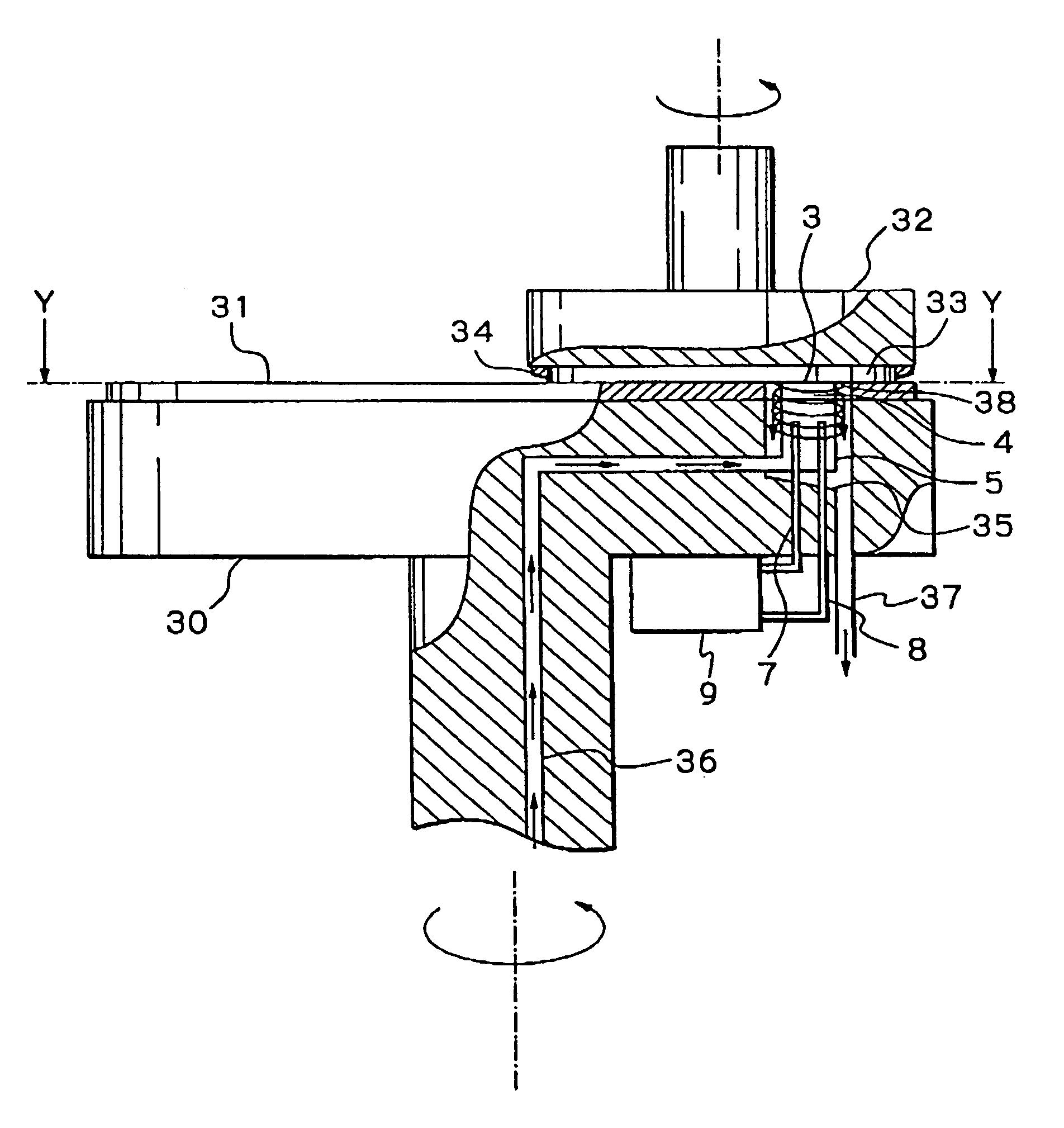
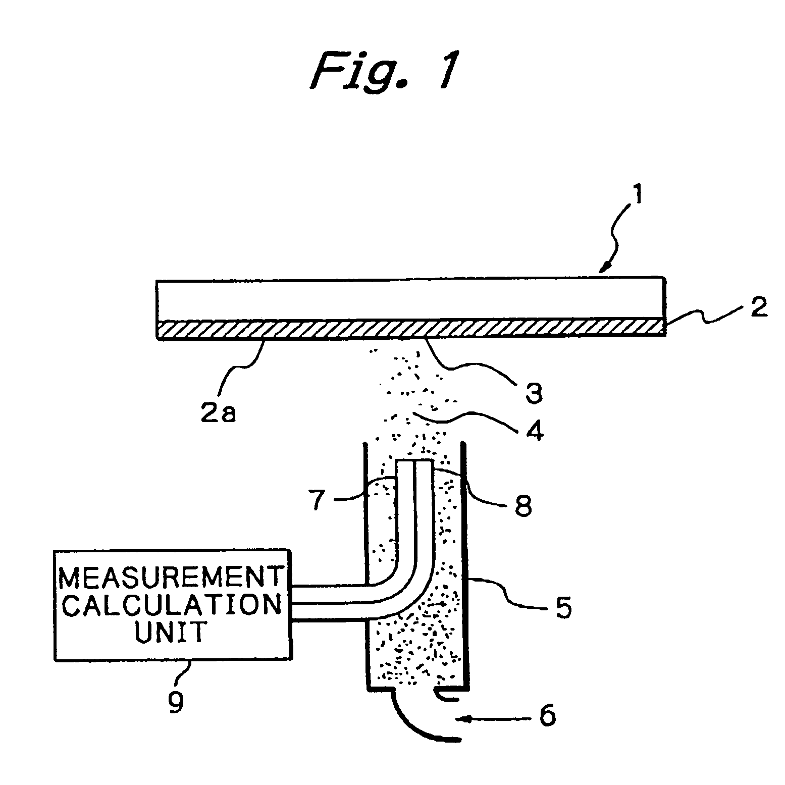
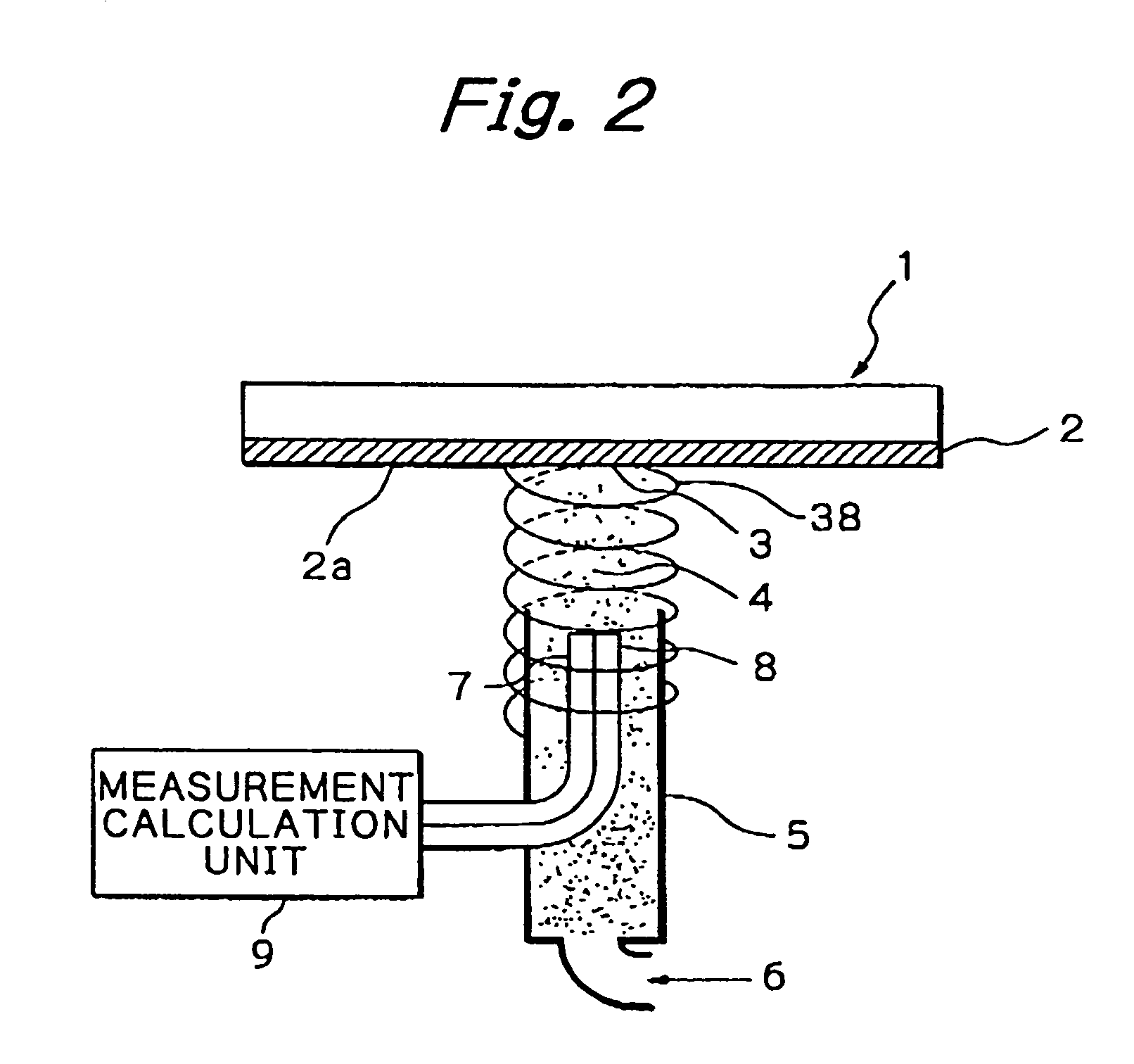
[0044]Embodiments of the present invention are described below, with reference to the drawings. FIG. 1 shows a general arrangement of a substrate film thickness measurement apparatus of the present invention. In FIG. 1, reference numeral 1 denotes a substrate having a thin film 2 formed thereon. Reference numeral 5 denotes a jet nozzle for supplying a jet of water in a cylindrical form onto a surface 2a of the substrate 1 on a side to be processed. Respective distal end (i.e., the end closest to the film 2) portions of a light-emitting optical fiber 7 and a light-receiving optical fiber 8 are provided within the jet nozzle 5.

[0045]In the above-mentioned substrate film thickness measurement apparatus, pressurized water 6 is supplied to the jet nozzle 5. A water jet 4 is supplied in a cylindrical form having a small diameter from a distal end of the jet nozzle 5 onto a predetermined position on the surface 2a of the substrate 1, to thereby form a measurement spot 3. In this state, lig...


PUM


Abstract

A jet of water in a cylindrical form is supplied from a jet nozzle onto a measurement surface of a substrate to form a column of the water extending between the nozzle and the measurement surface. Light is emitted from an irradiation fiber and transmitted through the column of water to the measurement surface. The light reflected by the measurement surface is received by a light-receiving fiber through the column of water. A measurement calculation unit measures the thickness of a film formed on the substrate, based on the intensity of the reflected light.

Description

[0001]This is a divisional application of Ser. No. 09 / 734,737, filed Dec. 13, 2000, now U.S. Pat. No. 6,785,010.BACKGROUND OF THE INVENTION[0002]The present invention relates to a method and an apparatus for measuring the thickness of a film on a substrate, and a substrate processing apparatus utilizing the same. The method and apparatuses of the present invention can be advantageously employed especially in effecting real-time detection and monitoring of a film thickness of a substrate on a side being processed during processing. It should be noted that “measurement of a film thickness of a substrate” in the present invention means not only measurement of a film thickness of a substrate, but also detection or observation of a condition of the substrate, such as the presence or absence of a metallic thin film formed on the substrate.[0003]As a conventional technique of the above-mentioned type, Unexamined Japanese Patent Application Public Disclosure (Kokai) No. 7-251371 discloses t...

Claims


Application Information

Patent Timeline
IPC IPC(8): G01B11/28B24B37/013B24B49/12G01B11/06H01L21/304H01L21/306H01L21/66
CPCB08B1/04B24B37/013G01B11/0683G01B11/0625B24B49/12B08B1/32H01L22/00
Inventor KIMBA, TOSHIFUMINAKAI, SHUNSUKE
Owner EBARA CORP
Learn More