Check patentability & draft patents in minutes with Patsnap Eureka AI!

Reduced power registered memory module and method

a memory module and power register technology, applied in the direction of information storage, static storage, digital storage, etc., can solve the problems of constant demand for memory capacity and speed, power consumption each, and inability to meet the requirements of ever increasing memory capacity and speed

Inactive Publication Date: 2006-07-04
ROUND ROCK RES LLC
View PDF59 Cites 17 Cited by
  • Summary
  • Abstract
  • Description
  • Claims
  • Application Information

AI Technical Summary

Benefits of technology

"The registered memory module described in this patent allows for efficient use of power by only consuming significant power when there is a memory access directed to a specific memory device. The module includes a register that stores input signals based on a transition of an internal clock signal, and a logic circuit that determines which memory device to access based on select signals. This results in a more efficient and effective memory module for use in various applications."

Problems solved by technology

However, power is consumed each time a digital circuit is switched to change the state of a signal line.
Thus, the demands for ever increasing memory capacities and speeds are inconsistent with the demands for ever decreasing memory power consumption.
Excessive power consumption can also create problems even where DRAM devices are not powered by batteries.
For example, the heat generated by excessive power consumption can damage the DRAM devices, and it can be difficult and / or expensive to maintain the temperature of electronic equipment containing the DRAM devices at an acceptably low value.
While this approach can significantly reduce the power consumed by DRAM devices, there are circuits in DRAM devices that cannot be rendered inactive without compromising the speed and / or operability of the DRAM devices.
Therefore, the power consumed by the modules 10a-c that are not being selected for the memory access is unnecessarily consumed.

Method used


Image

  • Reduced power registered memory module and method
  • Reduced power registered memory module and method
  • Reduced power registered memory module and method

Examples


Embodiment Construction

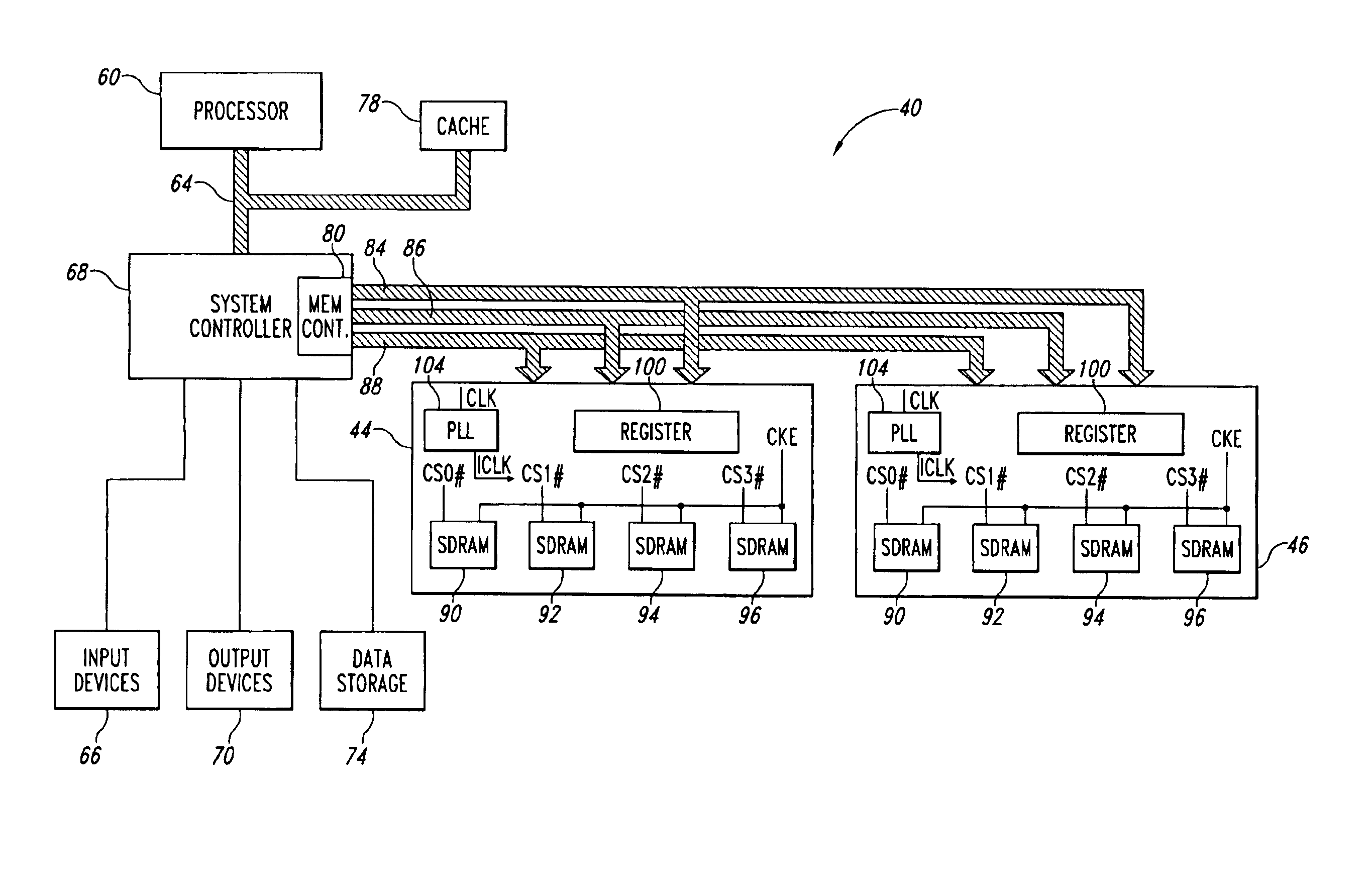
[0015]A computer system 40 containing two registered DRAM modules 44, 46 in accordance with one embodiment of the invention is shown in FIG. 3. The computer system 40 includes a processor 60 for performing various computing functions, such as executing specific software to perform specific calculations or tasks. The processor 60 is coupled to a processor bus 64 that normally includes an address bus, a control bus, and a data bus. In addition, the computer system 40 includes one or more input devices 66, such as a keyboard or a mouse, coupled to the processor 60 through a system controller 68 to allow an operator to interface with the computer system 40. Typically, the computer system 40 also includes one or more output devices 70 coupled to the processor 60 through the system controller 68, such output devices typically being a printer or a video terminal. One or more data storage devices 74 are also typically coupled to the processor 60 through the system controller 68 to allow the...


PUM


Abstract

A registered memory module includes a plurality of flip-flops having respective data terminals, respective clock terminals receiving a clock signal and output terminals coupled to a plurality of SDRAM devices in the module. A logic gate decodes respective chip select signals for selecting the SDRAM devices. The logic gate generates an enable signal if a memory access is being directed to any of the SDRAM devices in the module. In one embodiment, the flip-flops include an enable input coupled to receive the enable signal from the logic gate. In another embodiment, the input signals are coupled to the data inputs of the flip-flops through logic gates that are selectively enabled by the enable signal from the logic gate. As a result, the input signals are not latched by transitions of the clock signal when a memory access is not directed to any of the SDRAM devices in the module.

Description

CROSS-REFERENCE TO RELATED APPLICATION[0001]This application is a continuation of U.S. patent application Ser. No. 10 / 165,821, filed Jun. 7, 2002 now U.S. Pat. No. 6,731,548.TECHNICAL FIELD[0002]The invention relates to dynamic random access memory devices, and, more particularly, to a method and system for reducing the power consumed by registered memory modules.BACKGROUND OF THE INVENTION[0003]Dynamic random access memory (“DRAM”) devices are commonly used in a wide variety of applications. One of the most common use for DRAM devices is as system memory in personal computers. The speed and capacity demands on DRAM devices continues to increase in this and other applications. However, power is consumed each time a digital circuit is switched to change the state of a signal line. The rate at which power is consumed by DRAM devices therefore increases with both the capacity and the operating speed of the devices. Thus, the demands for ever increasing memory capacities and speeds are ...

Claims


Application Information

Patent Timeline
Patent Type & Authority Patents(United States)
IPC IPC(8): G11C7/00G11C7/10
CPCG11C5/04G11C7/1072G11C7/1078G11C11/4076G11C7/109G11C7/22G11C7/222G11C7/1087
Inventor PAX, GEORGE E.
Owner ROUND ROCK RES LLC
Features
  • R&D
  • Intellectual Property
  • Life Sciences
  • Materials
  • Tech Scout
  • Unparalleled Data Quality
  • Higher Quality Content
  • 60% Fewer Hallucinations
Learn More