
Filter coefficient setting technique for variable filtering process and variable sampling frequency conversion

a filter coefficient and variable filtering technology, applied in the field of filter coefficient setting method and sampling frequency conversion method, can solve the problems of aliasing noise, unwelcome aliasing noise, and difficulty in realizing filters that can appropriately meet such requirements, and achieve the effect of enhancing the performance of the sampling frequency converter devi

Inactive Publication Date: 2006-07-04
YAMAHA CORP
View PDF3 Cites 22 Cited by
  • Summary
  • Abstract
  • Description
  • Claims
  • Application Information

AI Technical Summary

Benefits of technology

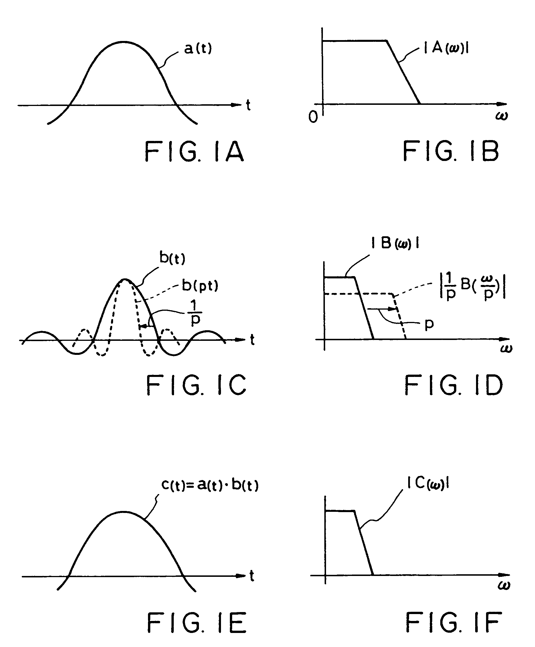
[0031]According to the above-mentioned arrangement, because the contents of the interpolation process are varied in correspondence to a ratio between the first and second sampling frequencies, the desired filter characteristic can be controlled in accordance with the ratio while only requiring a given first series of the filter coefficients to be prestored in a coefficient memory; besides, the filter characteristic control can always properly deal with a variation in the first or second sampling frequency, thereby greatly enhancing the performance of the sampling frequency converter device. If, for example, the given first series of filter coefficients is used directly, there arises the inconvenience that the filter characteristic would undesirably vary as the first or second sampling frequency is changed, as noted earlier in connection with the conventional technique. However, by varying the contents of the interpolation process in correspondence to a ratio between the first and second sampling frequencies in such a manner that an impulse response characteristic of the resultant second series of filter coefficients is expanded or compressed on the time axis, the present invention can control a desired filter characteristic (e.g., cutoff frequency) to not vary even when the first or second sampling frequency is changed.

Problems solved by technology

For example, in a case where the intended sampling frequency after the conversion (after-conversion sampling frequency) is “f2”, if the input digital signal waveform passed to the interpolation filter 2 contains spectral components higher than f2 / 2, these spectral components would cause aliasing noise.
However, this approach would encounter the following problems due to disagreement between a half (½) of the after-conversion sampling frequency f2 and the high cutoff frequency fc.
As a result, unwanted aliasing noise would result from the sampling frequency conversion to the sampling frequency f2 performed by the interpolation filter 2.
However, due to a limited storage capacity of the coefficient memory 3, it has been extremely difficult to realize a filter that can appropriately meet such a requirement.
However, the conventional filter interpolating techniques can not freely vary filter characteristics to be achieved, and can just prestore fewer filter coefficients than those necessary for the filter characteristics to be achieved and make up for the insufficiency by interpolating between prestored filter coefficients.

Method used


Image

  • Filter coefficient setting technique for variable filtering process and variable sampling frequency conversion
  • Filter coefficient setting technique for variable filtering process and variable sampling frequency conversion
  • Filter coefficient setting technique for variable filtering process and variable sampling frequency conversion

Examples


Embodiment Construction

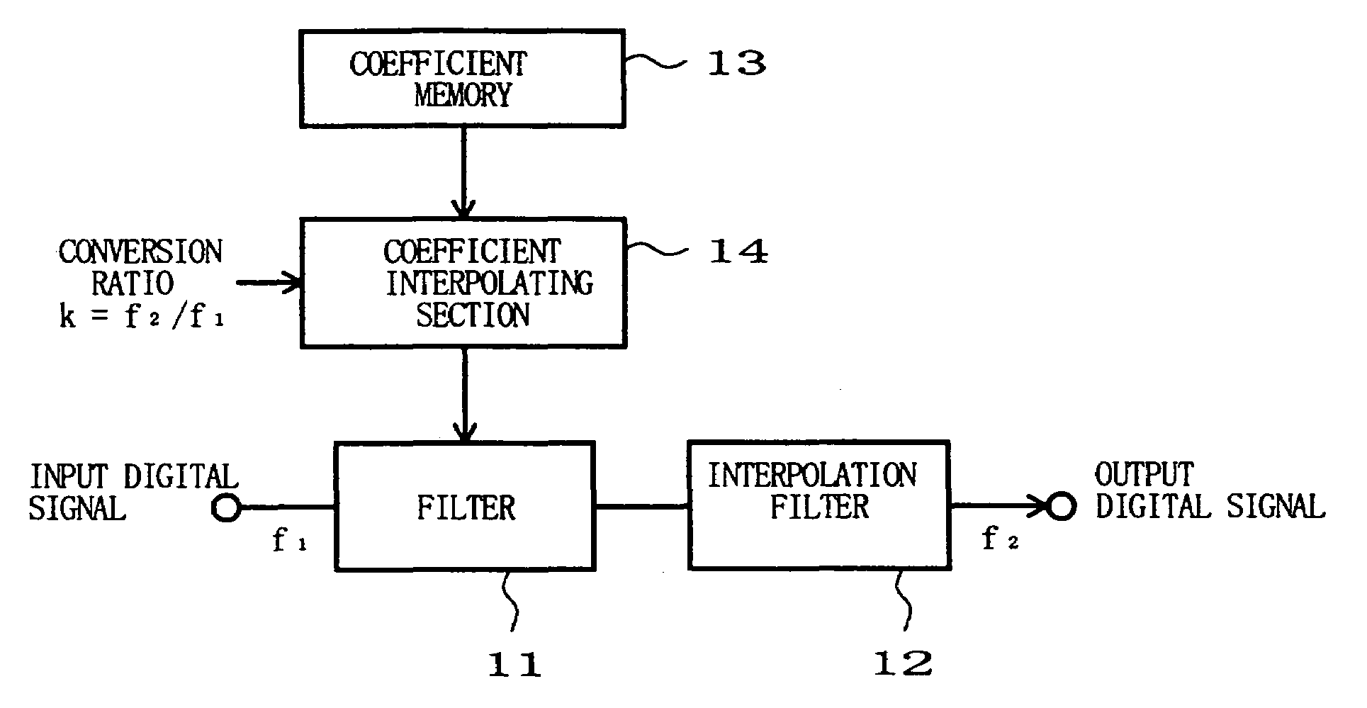
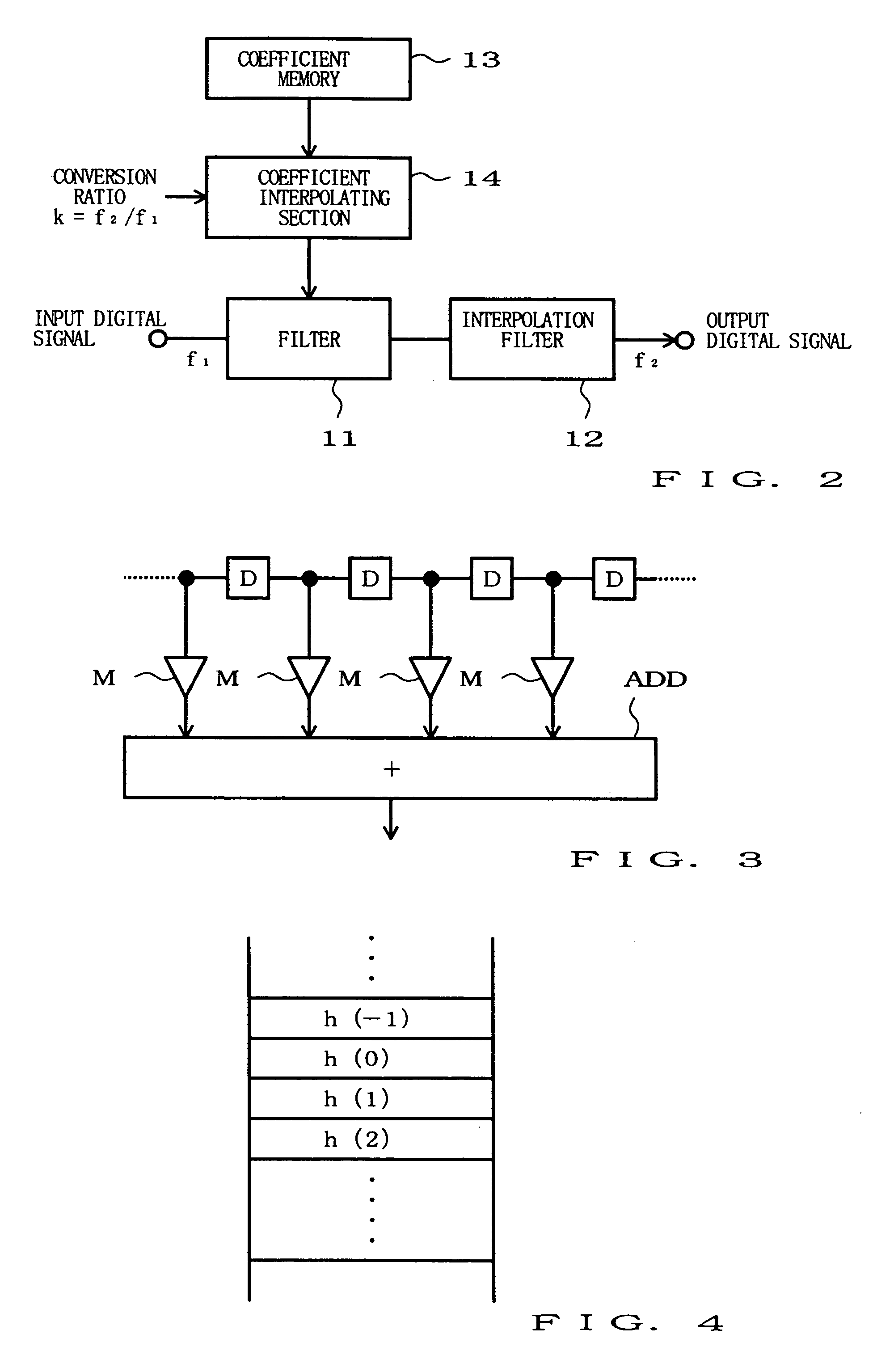
[0042]FIG. 2 is a block diagram showing an exemplary setup of a sampling frequency converter device in accordance with a preferred embodiment of the present invention. As shown, the convertor device comprises a filter 11, an interpolation filter 12, a coefficient memory 13 and a coefficient interpolating section 14.

[0043]Like the filter 1 mentioned earlier in relation to FIG. 10, the filter 11 preceding the interpolation filter 12 operates to previously eliminate, from input digital signals of sampling frequency f1, high-frequency components (high-frequency signals) so as to prevent unwanted aliasing noise. In the present embodiment, the filter 11 is in the form of a FIR (Finite-duration Impulse-Response) filter that comprises delay circuits D, D, . . . , multipliers M, M, . . . and an adder ADD, although the filter 11 may be constructed in any other manner. Although not specifically shown, the filter 11 includes a variable-gain amplifier at its output end. Like the interpolation fi...


PUM


Abstract

A first series of filter coefficients stored in a memory itself corresponds to a given filter characteristic such as a given high cutoff frequency. A second series of filter coefficients is generated by performing an interpolation process on the first series of filter coefficients. At that time, the contents, such as interpolation coefficients, of the interpolation process are varied in correspondence to a desired filter characteristic to be achieved, so that the interpolation process generates a second series of filter coefficients according to an impulse response characteristic that is obtained as a consequence of expanding or compressing, in a time-axis direction, an impulse response characteristic represented by the given first series of the filter coefficients. Thus, by the interpolation process, there is produced such a second series of filter coefficients that achieves a different filter characteristic (e.g., different high cutoff frequency). Where the sampling frequency of a time series of digital signals is to be changed from a given first frequency to a second frequency, an aliasing noise frequency may vary depending on a value of the first or second sampling frequency, in which case it is necessary to vary the cutoff frequency of a filter for eliminating the aliasing noise. However, by performing the interpolation process in the above-noted manner, the filter characteristic for eliminating the aliasing noise can be varied as desired.

Description

BACKGROUND OF THE INVENTION[0001]The present invention relates to a method and device for setting filter coefficients, and a sampling frequency converting method and devices using these filter coefficient setting method and device.[0002]In general, digital signal processing systems for use in digital audio apparatuses are constructed to process digital signals of a predetermined sampling frequency. However, with recent development of multimedia technology, it sometimes becomes necessary to allow the digital signal processing systems to process digital signals of a different sampling frequency from the predetermined sampling frequency. To this end, a sampling frequency convertor device has so far been employed which converts the sampling frequency of the digital signals to properly fit the nature of processing to be performed by the digital signal processing system.[0003]In FIG. 10, there is shown an exemplary setup of such a conventional sampling frequency convertor device. As shown...

Claims


Application Information

Patent Timeline
Patent Type & Authority Patents(United States)
IPC IPC(8): H04B1/10H03H17/00H03H17/06
CPCH03H17/0685H03H17/0642
Inventor SOGO, AKIRA
Owner YAMAHA CORP
Learn More