Graphical user interface for display of anatomical information

a graphical user interface and anatomical information technology, applied in the field of system for rendering anatomical information, can solve the problems of difficult to use conventional x-ray systems to examine portions of the body, information about some of these structures is likely to be obscured, and the speed and accuracy of conventional x-ray systems are difficult to achieve. , to achieve the effect of optimizing the speed and accuracy

Inactive Publication Date: 2006-07-04
MEVIS MEDICAL SOLUTIONS
View PDF10 Cites 114 Cited by
  • Summary
  • Abstract
  • Description
  • Claims
  • Application Information

AI Technical Summary

Benefits of technology

[0026]In a preferred embodiment, the system is responsive to system user inputs in various display portions of a user interface. For example, one portion of an interface renders, or displays, a sequence of tomographic sections, the particular section or sections being displayed at any time being selectable by a scroll bar or scroll buttons. An additional portion of the interface display renders a volumetric view of a body including an indication on the view of a position on the body corresponding to the tomographic section then being rendered, or displayed, on the first portion of the display. An additional portion of the display ...

Problems solved by technology

Unfortunately, conventional x-ray systems have their limitations.
As a result, the image formed on the x-ray is only two-dimensional, and if multiple x-ray absorbing structures lie in the same shadow, information about some of these structures is likely to be obscured.
Moreover, in the case of medical applications, it is often quite difficult to use conventional x-ray systems to examine portions of the body such as the lungs that consist mostly of air when inflated and do not absorb x-rays significantly.
However, the cost of conventional CT equipment remains quite high (an average selling price in the United States of $800,000 per unit) and the cost per patient far ex...

Method used


Image

  • Graphical user interface for display of anatomical information
  • Graphical user interface for display of anatomical information
  • Graphical user interface for display of anatomical information

Examples


Embodiment Construction

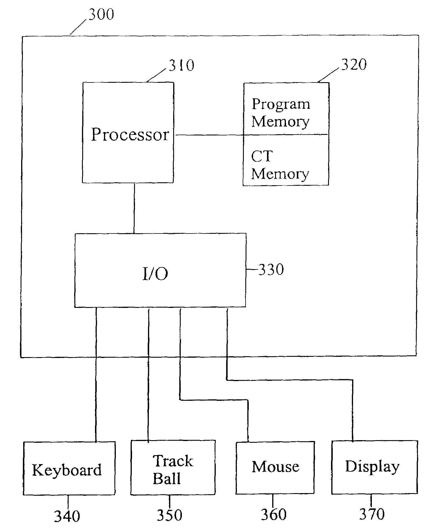
[0050]FIG. 3 is a block diagram of an illustrative computer system 300 useful in the practice of the invention. As shown, system 300 comprises a processor 310, a memory 320 and input / output interface 330. The input / output interface connects the processor to an input device (such as keyboard 340, a trackball 350, a mouse 360 and / or any other device capable of communicating and / or processing commands and inputs to the processor) and a display monitor 370. Illustratively, the processor is a 500 MHZ Intel Pentium III (Reg. TRANSCEIVER MODULE) dual microprocessor.

[0051]Memory 320 typically is a mixture of semiconductor random access memory (RAM), one or more hard disk drives and / or CD-ROM drives, perhaps a floppy drive, and one or more tape drives. Stored within memory 320 are an operating system, application programs and the data representative of one or more series of CT (or other three-dimensional datasets like MRI, ultrasound, PET) sections of one or more patients. Each series of CT ...


PUM


Abstract

A computer-aided diagnostic method and system provide image annotation information that can include an assessment of the probability, likelihood or predictive value of detected or identified suspected abnormalities as an additional aid to the radiologist. More specifically, probability values, in numerical form and/or analog form, are added to the locational markers of the detected and suspected abnormalities. The task of a physician using such a system as disclosed is believed to be made easier by displaying markers representing different regions of interest.

Description

[0001]The present application is a continuation-in-part of application Ser. No. 09 / 990,511, filed Nov. 21, 2001 now U.S. Pat. No. 6,925,200. application Ser. No. 09 / 990,511 claims priority to U.S. Provisional Application Ser. No. 60 / 314,582, filed Aug. 24, 2001, and claims priority to U.S. Provisional Application Ser. No. 60 / 252,743, filed Nov. 22, 2000.CROSS-REFERENCE TO RELATED APPLICATIONS[0002]Related applications are:[0003]“Density Nodule Detection in 3-Dimensional Medical Images,” application Ser. No. 09 / 993,792, filed Nov. 23, 2001;[0004]“Method and System for the Display of Regions of Interest in Medical Images,” application Ser. No. 09 / 990,508, filed Nov. 21, 2001;[0005]“Region Growing in Anatomical Images,” application Ser. No. 09 / 993,791, filed Nov. 23, 2001;[0006]“Automated Registration of 3-D Medical Scans of Similar Anatomical Structures,” application Ser. No. 09 / 993,790, filed Nov. 23, 2001;[0007]“Lung Field Segmentation from CT Thoracic Images,” application Ser. No. ...

Claims


Application Information

Patent Timeline
IPC IPC(8): G06K9/00A61B6/03G06F3/033G06F3/048G06T7/00G06T11/00G06T15/08G06V10/25
CPCA61B6/032A61B6/463A61B6/466G06F3/0481G06F3/04855G06K9/00G06K9/3233G06T7/0012G06T15/08G06T19/00A61B6/037Y10S378/901G06F2203/04805G06K2009/366G06K2209/05G06T2207/30061G06T2210/41G06T2219/004G06T2219/028G06V10/248G06V10/25G06V2201/03G06F18/00
Inventor WOOD, SUSAN A.ZHANG, HEIDICASPI, ANATDOI, TAKESHIROMSDAHL, HARLAN M.
Owner MEVIS MEDICAL SOLUTIONS
Why Eureka
Try Eureka