Image correction apparatus

a technology of image correction and apparatus, which is applied in the field of image correction apparatus, can solve the problems of requiring the provision of a very complex mechanism, the inability to always correct the captured image, and the limited luminance of the light sour

Inactive Publication Date: 2006-07-04
SHARP KK
View PDF41 Cites 72 Cited by
  • Summary
  • Abstract
  • Description
  • Claims
  • Application Information

AI Technical Summary

Benefits of technology

[0029]The invention is characterized in that the document shape computing means includes image reducing means for reducing an input image in accordance with a predetermined reduction rat

Problems solved by technology

However, the image forming apparatus disclosed in JP-A 57-191653 has had the problem that it requires the provision of a very complex mechanism, since the scan speed, the height of the document platen, and the luminance of the light source have to be limited while reading an image.
Furthermore, since results obtained by distance measuring means generally contain errors, there has been the problem that the result of the measurement does not agree with the actual distance between the document and the document platen and, as a result, the captured image cannot always be corrected so that it appears flat.
In the document reading apparatus disclosed in JP-A 5-161004, there is no need to detect the height of the document surface using distance measuring means such as a sensor as in the above-described image forming apparatus, and corrections for distortion and brightness are made on the basis of the image alone, but since the position of the boundary is uniquely associated with the document height, the document reading apparatus disclosed therein has had the problem that corrections cannot be made if the document is not placed in the specified position or if the document is placed by being rotated relative to that position.
A further problem has been that corrections cannot be made unless the document height is kept within a predetermined range along the main scanning direction of the reading means; only a warning is issued if the document height is not kept within the predetermined range along the main scanning direction of the reading means.
Further, with the prior art edge position detection method, as disclosed in JP-A 10-65877, if a connected component of an edge-detection filtered image is less than a predetermined value, it is judged to be an isolated point, and if the connected component is less than the predetermined value, interpolation is performed using a straight line; this method, however, has had the problem that edge detection errors and omissions of edge detection are liable to occur.
Therefore, this method has had the problem that if the document contains a localized irregularity such as a crease, such irregularity may be erroneously detected as the b

Method used


Image

  • Image correction apparatus
  • Image correction apparatus
  • Image correction apparatus

Examples


embodiment 1

[0054][Embodiment 1]

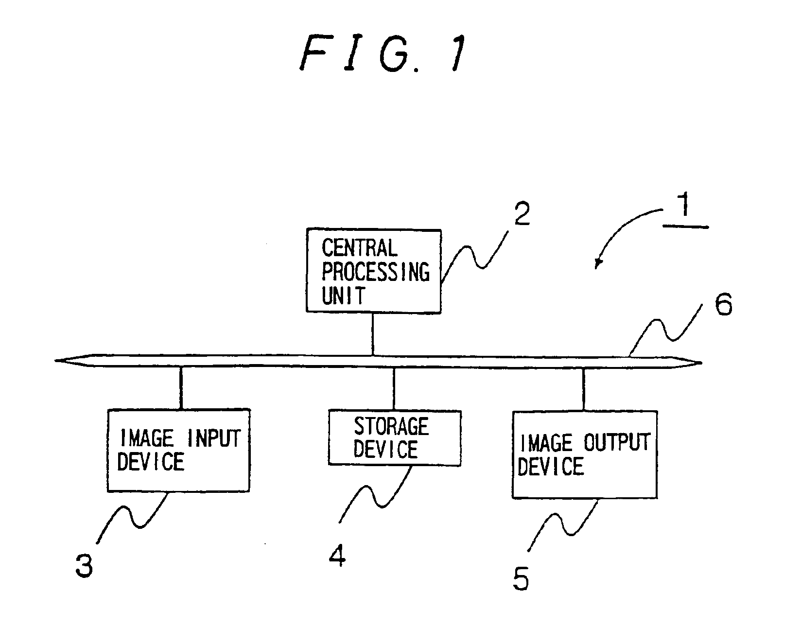
[0055]FIG. 1 is a block diagram showing the electrical configuration of an image correction apparatus 1 according to one embodiment of the present invention. The image correction apparatus 1 includes a central processing unit 2, an image input device 3, a storage device 4, and an image output device 5; these are interconnected by a bus line 6, and signals are transferred via the bus line 6. In the explanation hereinafter given, the description of the bus line will be omitted.

[0056]The image input device 3 as image input means is implemented, for example, by an image reading device such as a scanner. Alternatively, the image input device 3 may be implemented as a device for reading images prerecorded on a recording medium such as a CD-ROM (Compact Disk-Read Only Memory), a floppy disk, or an magneto optical disk.

[0057]The image output device 5 as image output means is implemented, for example, by a printer. Alternatively, the image output device 5 may be implement...

embodiment 2

[0099][Embodiment 2]

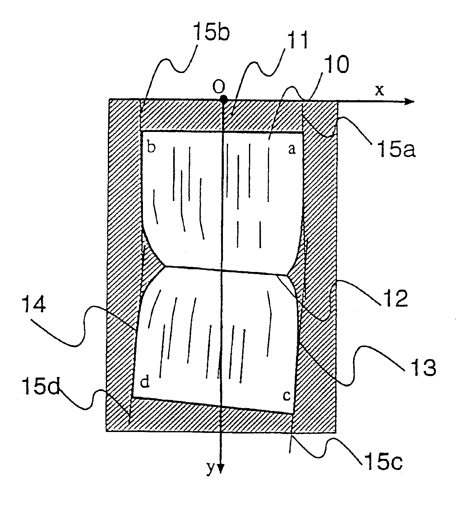
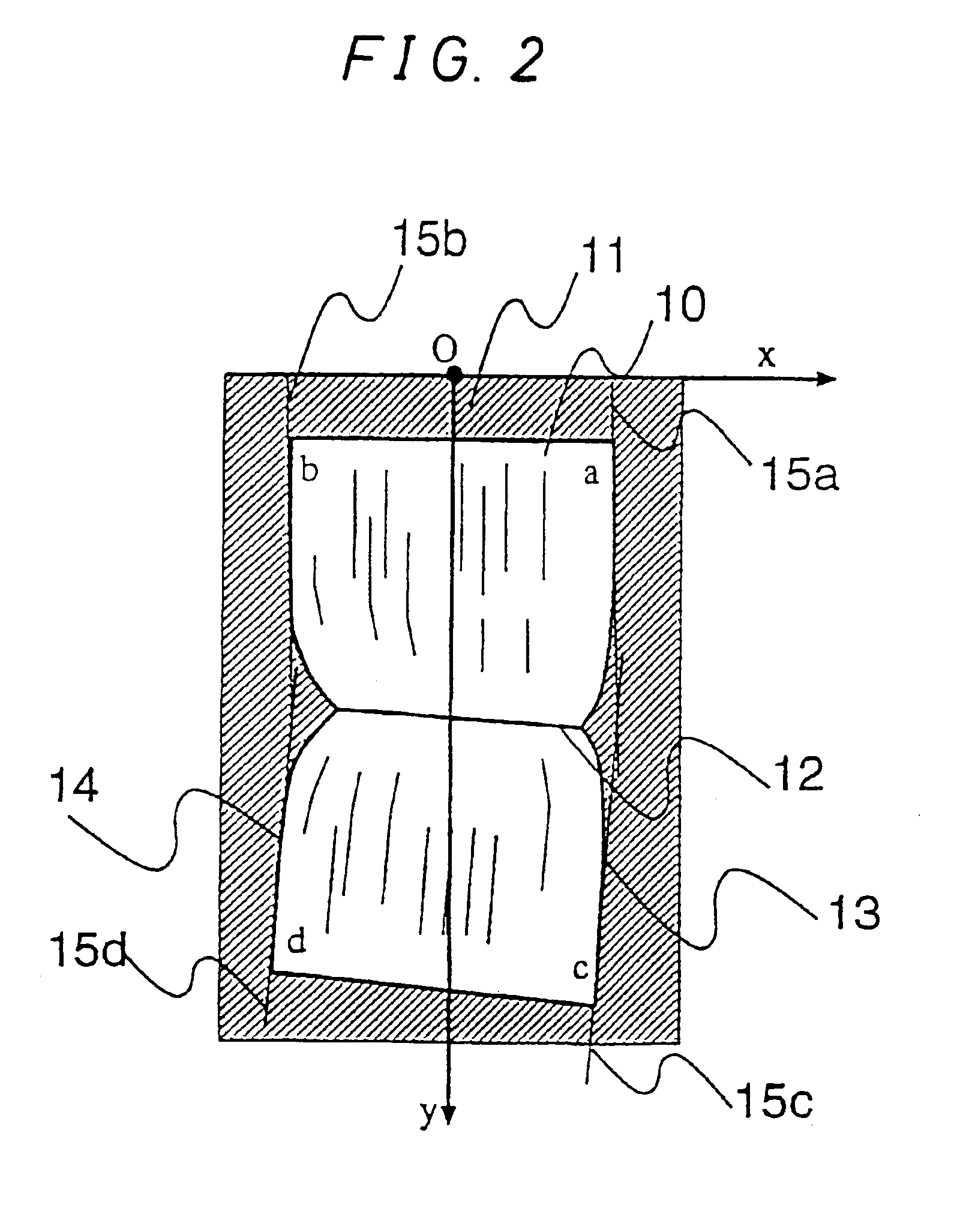
[0100]The second embodiment hereinafter described differs from the first embodiment in that image reducing means is added, and in that the document shape computing means used is different. In the present embodiment, the image reducing means and the document shape computing means are both implemented as programs run on the central processing unit 2, but each of these means may be implemented in hardware logic. The image reducing means takes an average over a plurality of pixels in an input image, and outputs it as one pixel. Alternatively, this can be accomplished by decimating pixels for output. In the first embodiment, the document shape is obtained from the input image, but since the resolution of an input image to a copying machine, etc. is very high, for example, 400 dpi or 600 dpi, if the document shape is to be obtained from such a high resolution image, there arises the problem that it takes a very large amount of memory and considerable computation time. ...

embodiment 3

[0104][Embodiment 3]

[0105]The third embodiment described hereinafter differs from the first embodiment by the inclusion of selecting means for making a selection as to whether image correction is to be performed or not, so that the input characteristics can be changed for the image to be input. The selecting means may be implemented as a selection menu in software or as a hardware switch. For example, when performing correction, the input image is corrected before being output, and when not performing correction, the input image is output as is. In an ordinary copying machine, the input characteristics are adjusted so that black characters appear black and white background appears white; on the other hand, in the image correction apparatus of the present invention, since document edges need to be detected, if images near the binding blacken, edges cannot be detected correctly. When performing distortion correction, if the image is input a little light, images near the binding do not...


PUM


Abstract

An image correction apparatus 1 includes an image input device 3, a memory device 4, a central processing unit 2, and and image output device 5. In the image correction apparatus 1, a locally wrinkled document or a document with a binding portion lifted differently between the top and bottom of the document is read from the image input device 3 and, using a program which is run on the central processing unit 2, an input image is corrected for the geometric distortion and luminance variations caused due to the upper and lower sides of the document making a slope with respect to a document platen, and thereby, a flat document image is restored.

Description

TECHNICAL FIELD[0001]The present invention relates to an image correction apparatus, and more particularly to an image correction apparatus which reads as an image a document having a locally distorted portion such as a portion in the vicinity of the binding edge of a book, and corrects the image as if the original document were flat.BACKGROUND ART[0002]Japanese Unexamined Patent Publication JP-A 57-191653 (1982) discloses an image forming apparatus as one example of an apparatus that produces clear copies at unity magnification of a document, such as a bound book or notebook, whose center binding portion, when placed on a document platen, is separated from the document platen. This image forming apparatus corrects image distortion and brightness by measuring the distance between the document and the document platen and by adjusting the scan speed, the height of the document platen, and the luminance of the light source in accordance with the measured distance; when a straight line ...

Claims


Application Information

Patent Timeline
IPC IPC(8): G06K9/36G06T1/00G06T5/00G06V30/10G06V30/146H04N1/387H04N1/40
CPCG06K9/32H04N1/387G06T5/006G06V30/10G06V30/146G06T1/00
Inventor NAKO, KAZUYUKI
Owner SHARP KK
Why Eureka
Try Eureka