
Method for clock synchronization validation in integrated circuit design

a clock synchronization and integrated circuit technology, applied in the direction of generating/distributing signals, program control, instruments, etc., can solve the problems of inefficient and time-consuming tasks, designer's significant time, and more complex circuits may be utilized for synchronization

Active Publication Date: 2006-07-04
SYNOPSYS INC
View PDF14 Cites 30 Cited by
  • Summary
  • Abstract
  • Description
  • Claims
  • Application Information

AI Technical Summary

Benefits of technology

The invention provides a better way to synchronize clocks in IC design. This can improve the accuracy and reliability of the design process. The invention can be used in a system, method, or computer program product.

Problems solved by technology

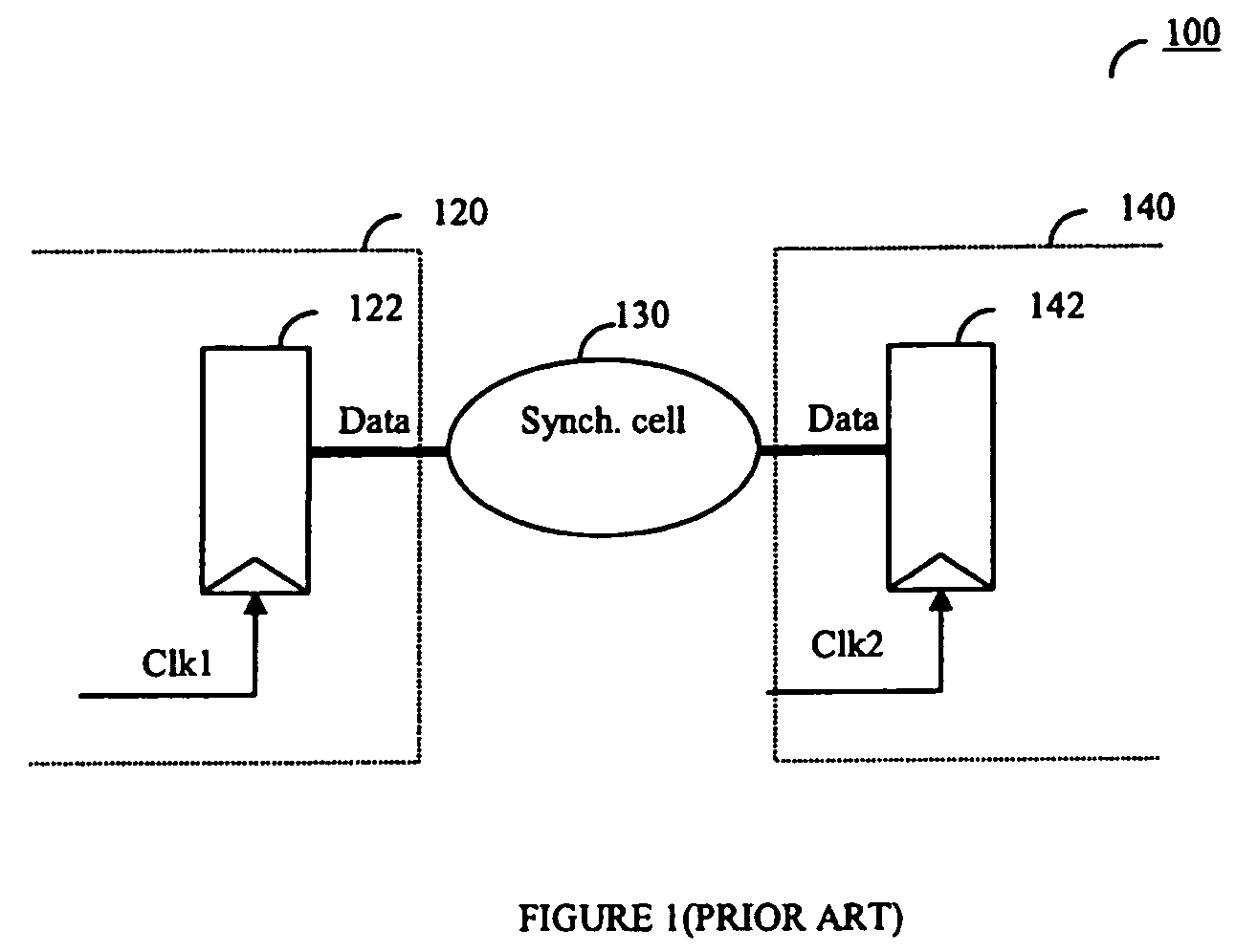
However, in some cases, more complex circuits may be utilized for synchronization cell 130, for example, a handshaking mechanism which may be a complex sequential circuit.
Clock synchronization validation in clock-crossing domains is one of the most important and difficult tasks in verification of large ICs.
Moreover, such tools generally identify all asynchronous clock domains that are not structurally verifiable as invalid asynchronous clock domains, even if those clock domains are well synchronized.
This requires the designer to spend significant time in verifying each asynchronous clock domain separately.
In typical ICs, where the number of clock-domain crossing may be large, this is an inefficient and a time-consuming task as well as being error prone.

Method used


Image

  • Method for clock synchronization validation in integrated circuit design
  • Method for clock synchronization validation in integrated circuit design
  • Method for clock synchronization validation in integrated circuit design

Examples


Embodiment Construction

[0015]The invention will now be taught using various exemplary embodiments. Although the embodiments are described in detail, it will be appreciated that the invention is not limited to just these embodiments, but has a scope that is significantly broader. The appended claims should be consulted to determine the true scope of the invention.

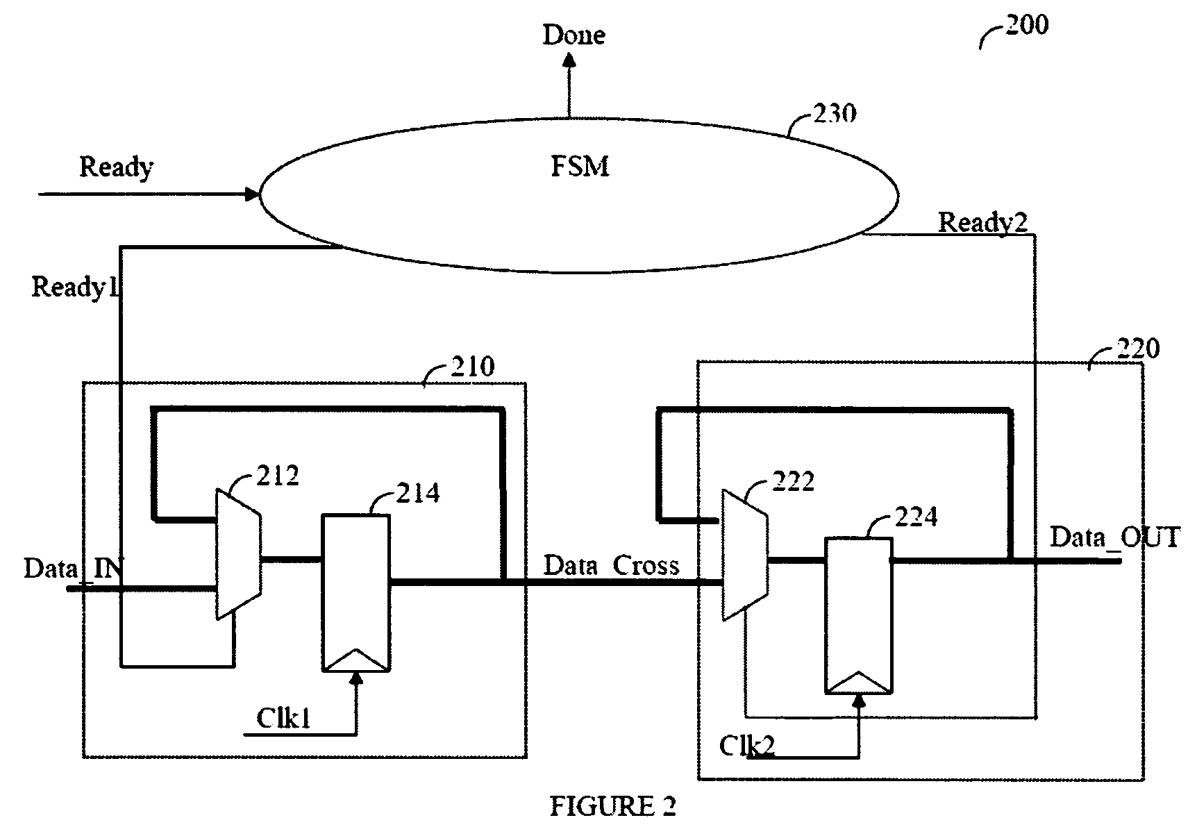
[0016]Reference is now made to FIG. 2 where an exemplary logic circuit 200 to be verified by the method for clock synchronization validation, is shown. Circuit 200 includes a first clock domain 210 and a second clock domain 220. The first clock domain 210 includes a MUX 212 and a register 214 clocked by clock signal “Clk1”. The second clock domain 220 includes a MUX 222 and a register 224 clocked by clock signal “Clk2”. Clock domain 210 sends data to clock domain 220 through a data bus “Data Cross”. Circuit 200 does not include a structural synchronization cell, such as a double-level register. There is a recirculation MUX (i.e., MUXs 212 and 222)...


PUM


Abstract

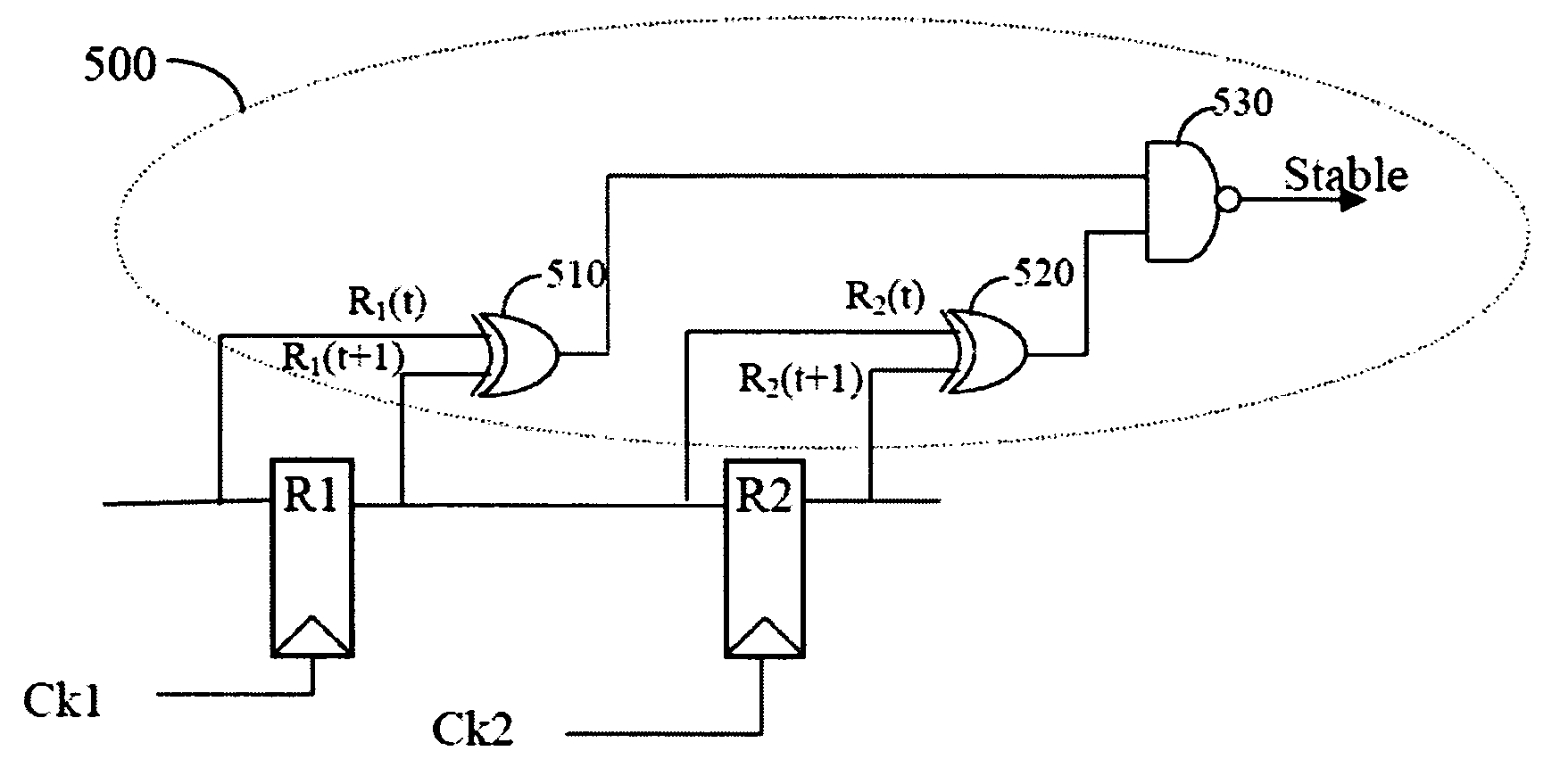
Unsynchronized clock-domain crossings in the design of integrated circuit are detected by searching for clock-crossing domains. For each clock-crossing that does not include an explicit synchronization cell, an analysis determines if the clock is stable crossing the domains.

Description

FIELD OF THE INVENTION[0001]The field of the invention is integrated circuit (IC) design, and more particularly to clock synchronization validation in IC design.BACKGROUND OF THE INVENTION[0002]In recent years the size of ICs has dramatically increased in both physical size and number of logical components. This has resulted in multiple clocks activating the logical components. In typical IC designs, a clock domain is defined as a set of all logical components (e.g., flip-flops, registers, synchronous RAM, and so on) that are clocked on the same edge of the same clock net. Clock domains that exchange data, also referred to as “clock-domain crossing” needed to be interfaced and synchronized in reliable and predictable ways to ensure the proper transfer of data from one clock domain to another.[0003]In the related art, there are several techniques for avoiding asynchronous clock-domain crossing and to reduce the probability of meta-stability. These techniques are based on adding a com...

Claims


Application Information

Patent Timeline
Patent Type & Authority Patents(United States)
IPC IPC(8): G06F9/45G06F17/50G06F1/12H04L7/00
CPCH04L7/0012G06F1/12
Inventor SARWARY, MOHAMED SHAKERMOVAHED EZAZI, MOHAMMADMURPHY, BERNARD
Owner SYNOPSYS INC
Learn More