
Fuel pressure control apparatus for multicylinder internal combustion engine

a multi-cylinder internal combustion engine and control apparatus technology, applied in the direction of electric control, fuel injecting pump, machine/engine, etc., can solve the problems of deteriorating durability, large volume of pressure chamber, and disadvantage in sliding surface wear resistance, so as to improve the reliability of high-pressure fuel pumps and increase cost.

Active Publication Date: 2006-07-11
MITSUBISHI ELECTRIC CORP
View PDF7 Cites 21 Cited by
  • Summary
  • Abstract
  • Description
  • Claims
  • Application Information

AI Technical Summary

Benefits of technology

[0027]The object of the present invention is to obtain a fuel pressure control apparatus for a multicylinder internal combustion engine which is capable of improving the reliability of a high pressure fuel pump by reducing a maximum fuel discharge amount without a large increase in cost while adopting the high pressure fuel pump with the number of cam crests=3 whose discharge cycle is at a speed lower than in the case of the number of cam crests=4.
[0029]In addition, in case where the maximum fuel discharge amount is not reduced but set to the same amount as that in a conventional apparatus, the present invention can be applied to a high power internal combustion engine particularly with a large maximum fuel injection amount without deteriorating durability.

Problems solved by technology

However, a maximum fuel injection amount substantially at least twice as much as the maximum fuel discharge amount is needed, so there is a problem that the volume of the pressure chamber is enlarged, and the maximum fuel discharge amount, being substantially large, increases stress on the contact surfaces between the cam and the plunger thereby to deteriorate durability.
Therefore, the discharge period becomes higher speed (i.e., shorter) than at the time of the number of cam crests=2, thus resulting in a disadvantage in terms of wear resistance in the sliding surfaces between the plunger and the pump cylinder and in the contact surfaces between the plunger and the cam, as compared with the case of the number of cam crests=2.
Besides, since the maximum fuel discharge amount corresponding to twice the maximum fuel injection amount is needed, as in the case of the number of cam crests=2, there still remains the problem that the volume of the pressure chamber is enlarged, and stress on the contact surfaces between the cam and the plunger is increased to deteriorate durability.
However, since the fuel discharge cycle is a period equal to twice the number of revolutions per minute of the engine (i.e., four discharges for every two revolutions of the four-cylinder internal combustion engine), the discharge cycle becomes the highest speed, thus causing a problem that wear resistance in the sliding surfaces between the plunger and the pump cylinder and in the contact surfaces between the plunger and the cam is deteriorated.
Thus, in order to improve the reliability of the high pressure fuel pump, it is desirable to increase the fuel discharge period and reduce the maximum fuel discharge amount, but there arises a problem that in case where such a scheme is intended to be applied to a high power internal combustion engine, it becomes difficult to provide durability and wear resistance of the high pressure fuel pump, thereby making it impossible to ensure reliability.
However, it is difficult to improve reliability more than the present state without any great increase in cost.
In particular, there is a problem that in case of high power four-cylinder internal combustion engines in which the maximum fuel injection amount is further increased, it is impossible to make durability and wear resistance of the high pressure fuel pump compatible with each other.
In this case, however, a large increase in cost will be induced, and it can not be said a practical method of solution at all even from the viewpoint of installation.
In the known fuel pressure control apparatuses for a multicylinder internal combustion engine, in case of the number of cam crests of the high pressure fuel pumps being equal to 2, the maximum fuel discharge amount corresponding to twice the maximum fuel injection amount is required and hence there has been the problem that the volume of the pressure chamber is enlarged, and the maximum fuel discharge amount, being substantially large, increases stress on the contact surfaces between the cam and the plunger thereby to deteriorate durability.
In addition, in case of the number of cam crests=3 or 4, the discharge period becomes high speed (i.e., short), resulting in a disadvantage in terms of wear resistance on the sliding surfaces between the plunger and the pump cylinder and on the contact surfaces between the plunger and the cam.
Besides, there is also the problem that the volume of the pressure chamber is enlarged, and stress on the contact surfaces between the cam and the plunger is increased to deteriorate durability, as in the case of the number of cam crests=2.

Method used


Image

  • Fuel pressure control apparatus for multicylinder internal combustion engine
  • Fuel pressure control apparatus for multicylinder internal combustion engine
  • Fuel pressure control apparatus for multicylinder internal combustion engine

Examples


embodiment 1

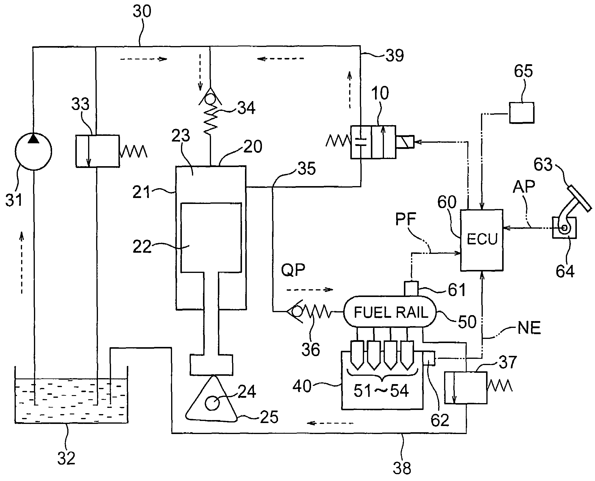
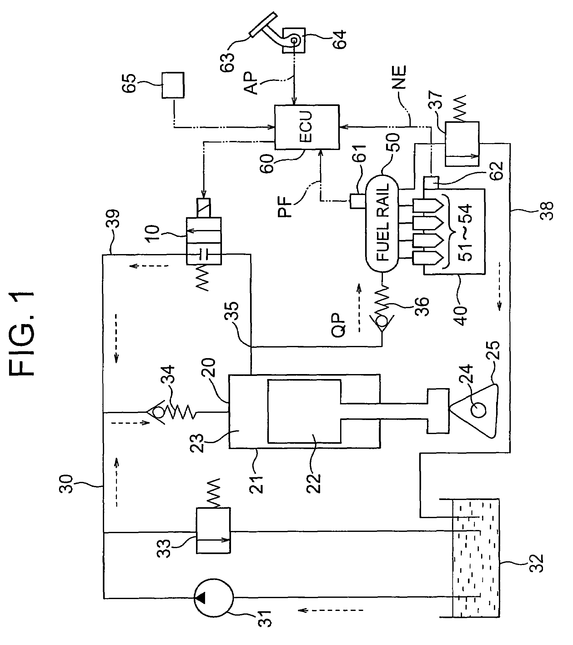
[0042]Hereinafter, reference will first be made to a fuel pressure control apparatus for a multicylinder internal combustion engine according to a first embodiment of the present invention while referring to the accompanying drawings. FIG. 1 is a block diagram that illustrates the fuel pressure control apparatus for a multicylinder internal combustion engine according to the first embodiment of the present invention.

[0043]Here, reference will be made to the fuel pressure control apparatus for a multicylinder internal combustion engine with the number of cylinders being M (M being a natural number not less than 2, and in particular M being set to 4 in this example) while using a high pressure fuel pump which has N fuel discharge strokes (in general, N being a natural number not less than 1, N20 for pressurizing fuel to a high pressure is provided with a cylinder 21, a plunger 22 that is received to reciprocate in the cylinder 21, and a pressure chamber 23 that is defined by an inner ...

embodiment 2

[0105]Though not specifically referred to in the above-mentioned first embodiment, in an internal combustion engine having a rotational phase adjustment section for adjusting the rotational phase of the camshaft 24 relative to the crankshaft, it is desirable to preset the positional relation of the first and second calculation timings so as not to change the order of occurrence of the first and second calculation timings when the rotational phase of the camshaft 24 relative to the rotational phase of the crankshaft is adjusted to the most retarded angle side or to the most advanced angle side.

[0106]Hereinafter, reference will be made to a second embodiment of the present invention that is applied to an internal combustion engine having a rotational phase adjustment section. The overall construction of a fuel pressure control apparatus for a multicylinder internal combustion engine according to the second embodiment of the present invention is the same as the one shown in FIG. 1 exce...


PUM


Abstract

A fuel pressure control apparatus for a multicylinder internal combustion engine includes fuel injection valves arranged one for each of M cylinders (M≧3), a fuel rail, a high pressure fuel pump performing N (≧2) fuel discharge strokes to the fuel rail during a fuel injection stroke makes a round of the cylinders, a fuel discharge amount control valve, an FF amount calculation section for calculating the fuel discharge amount based on the fuel injection amount, and a fuel discharge amount control section for determining the fuel discharge amount based on the FF amount and setting the drive timing of the fuel discharge amount control valve. The fuel injection amount multiplied by M / N is used as an FF amount in the fuel discharge amount three times while the fuel injection stroke makes a round of the cylinders.

Description

BACKGROUND OF THE INVENTION[0001]1. Field of the Invention[0002]The present invention is a fuel pressure control apparatus for a multicylinder internal combustion engine which is capable of injecting fuel into respective cylinders of the multicylinder internal combustion engine while controlling the pressure of fuel in a fuel rail at a high pressure. More particularly, the invention relates to such a fuel pressure control apparatus for a multicylinder internal combustion engine that is provided with a high pressure fuel pump having N (N<M) times of fuel discharge stroke with respect to the fuel rail during one round of the fuel injection stroke to M pieces of cylinders.[0003]2. Description of the Related Art[0004]In recent years, there has been put into practical use internal combustion engines in which the pressure of fuel in a fuel rail is controlled to a desired target high pressure value so as to inject the fuel in an atomized state (see, for example, a first patent document ...

Claims


Application Information

Patent Timeline
IPC IPC(8): F02M69/54F02M69/46
CPCF02D41/3845F02M63/023F02M63/0245F02M63/0265F02M63/0225F02D2041/141F02M59/102F02D2250/12
Inventor OONO, TAKAHIKO
Owner MITSUBISHI ELECTRIC CORP
Learn More