Gas spring

a technology of gas springs and springs, applied in the direction of springs, vibration dampers, liquid springs, etc., can solve the problems of complete blockage and negatively affect the closing behaviour, and achieve the effect of excellent controllable stroke behaviour

Inactive Publication Date: 2006-07-11
SUSPA
View PDF22 Cites 12 Cited by
  • Summary
  • Abstract
  • Description
  • Claims
  • Application Information

AI Technical Summary

Benefits of technology

[0005]It is an object of the present invention to develop a gas spring in such a way that excellently controllable stroke behaviour is obtained.
[0007]The gist of the invention firstly resides in integrating a velocity-dependent damping device in the gas spring. U.S. Ser. No. 09 / 412,356 teaches a damper characterized by velocity-dependent damping. In this damper, high closing velocities will have a strongly increased damping effect, possibly leading to complete blockage. A damper of this type, when used in a closing device, may negatively affect the closing behaviour. For this to be avoided, velocity-dependent dampers are as a rule designed for action only from a comparatively high velocity of stroke onwards. This will not always reliably preclude any breakdown of the closing element the closing motion of which the damper is intended to attenuate. The damper of U.S. Ser. No. 09 / 412,356 has therefore been improved according to the invention by integration of a path-dependent damping device. The invention proceeds from the experience that a gas spring that provides for a path-dependent damping effect in addition to velocity-dependent damping will adapt optimally to the respective requirements of incorporation as far as controllability of the motion of stroke of its damping piston is involved. When used in an engine hood or tailgate, the gas spring according to the invention will accomplish a stopping effect, the damping characteristic of which simultaneously depending on the velocity and path of closing. Prior to the hood or gate slamming shut, an increased damping effect may be obtained reliably by the additional path-dependent damping, reducing the closing velocity to a range far below the threshold that would spark velocity-dependent damping. The result is a gas spring of excellently controllable and reliable operating behaviour. When used in an engine hood or tailgate, it will in particular prevent any breakdown. Components such as stops for breakdown protection can be dropped. There is no longer any need for joint enlargement between adjacent components. It is possible, by the aid of the velocity-dependent damping device on the one hand and the path-dependent damping device on the other, to set the damping characteristic for conveniently increased acoustic ambience accompanying any motion of stroke of the gas spring. Additional measures for the reduction of manufacturing tolerances can be dropped.
[0008]A gas spring, in which the path-dependent damping device is embodied for stronger damping of the motion of stroke in an area of two end positions thereof than in an area of the remaining stroke, offers some increase in damping especially in the final range of push-in motion so that any damages by component parts colliding in the end position can be precluded.
[0010]A path-dependent damping device can easily be put into practice from a manufacturing point of view when being embodied as a damping-fluid passage of path-dependently varying cross section between the two sectional casing chambers, with the cross section of the damping-fluid passage in the area of one of the two end positions of the stroke being smaller than it is in the area of the remaining stroke.
[0011]In this case, a multistage damping effect can easily be obtained by the variation of the cross section of the damping device taking place in several steps.

Problems solved by technology

In this damper, high closing velocities will have a strongly increased damping effect, possibly leading to complete blockage.
A damper of this type, when used in a closing device, may negatively affect the closing behaviour.

Method used


Image

  • Gas spring
  • Gas spring
  • Gas spring

Examples


Embodiment Construction

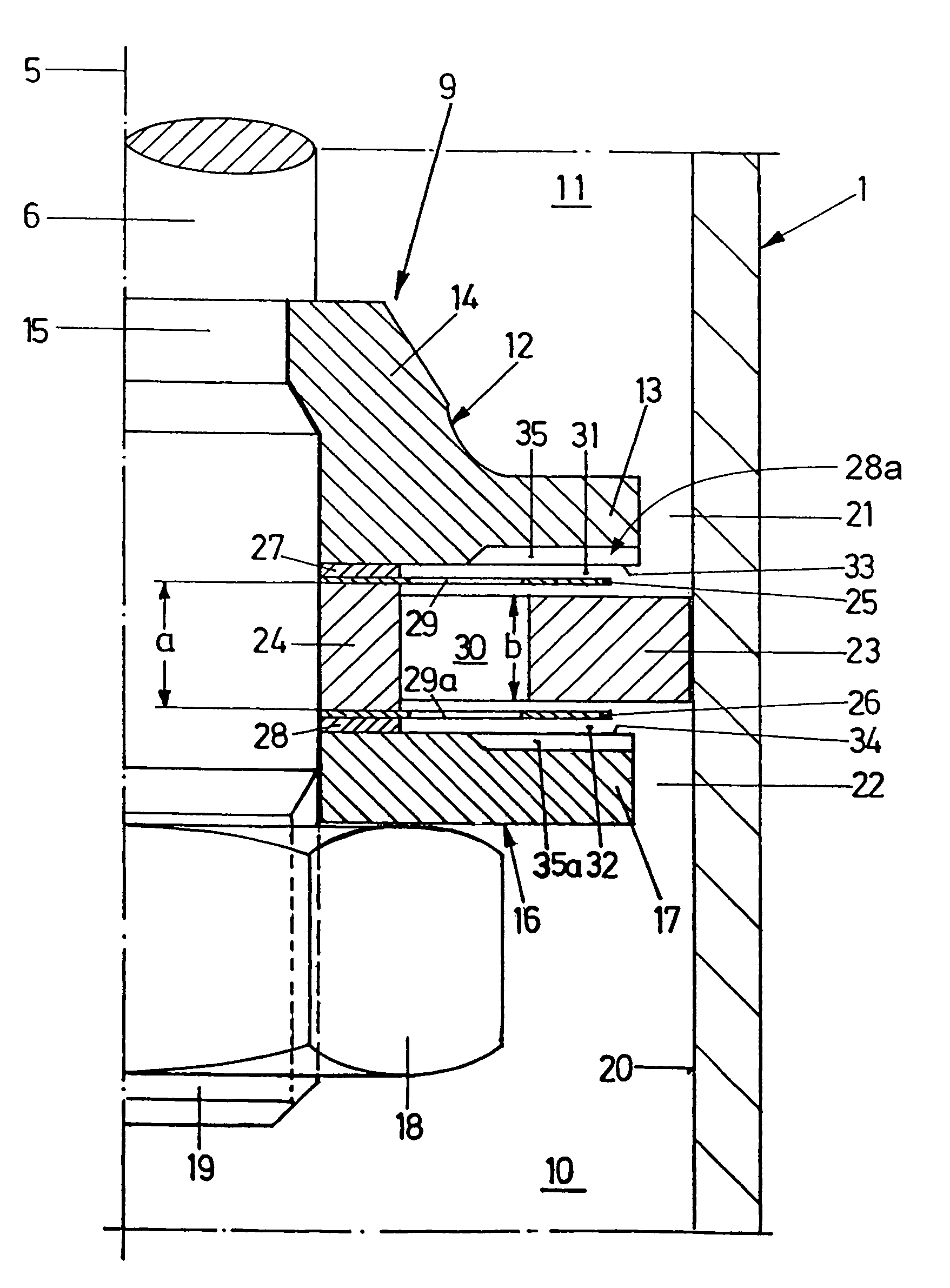
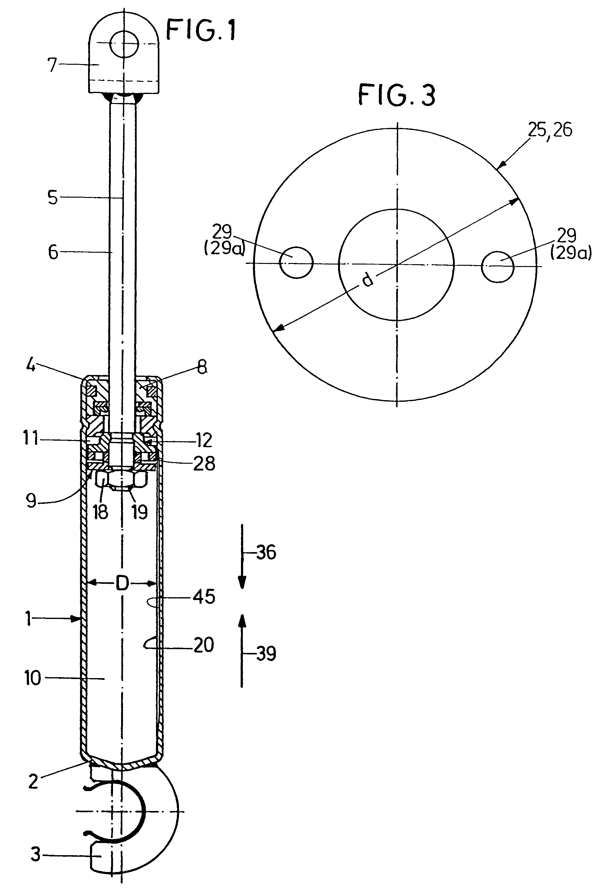
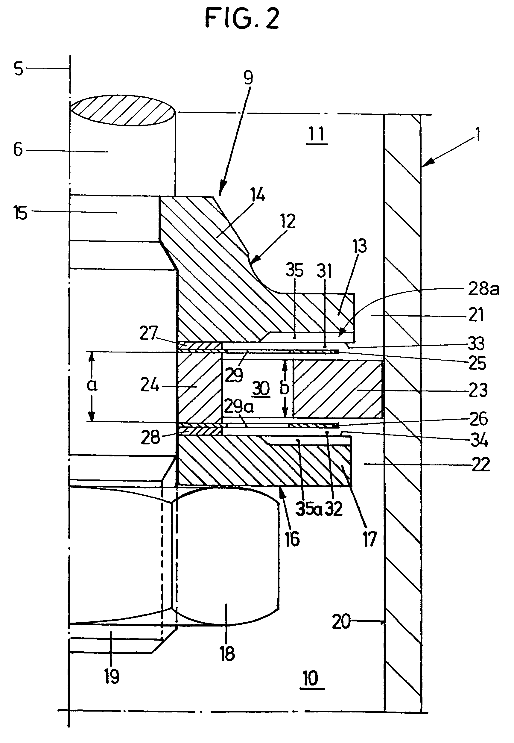
[0026]The gas spring seen in FIG. 1, which is for example a tailgate gas spring, comprises a substantially cylindrical casing 1 in the form of a tube, one end of which is closed by a bottom 2. The casing 1 is filled with compressed gas as a gas-spring energy storing device. A claw-type fastening element 3 is mounted on the bottom 2. At the end 4 opposite the bottom 2, a piston rod 6 is extended out of the casing 1; it is coaxial with the central longitudinal axis 5 of the casing 1. The outer free end of the piston rod 6 comprises another fastening element 7. At the end 4, the piston rod 6 is guided by a guide and seal unit 8 in a liquid- and gasproof manner for displacement in the direction of the axis 5.

[0027]The end, inside the casing 1, of the piston rod 6 is provided with a damping piston 9 which is going to be described in detail below. This damping piston 9 divides the interior of the casing 1 into two sectional casing chambers 10, 11, the sectional chamber 10 of which being f...


PUM


Abstract

A gas spring comprises a cylindrical casing, in which a piston rod is guided for displacement concentric of a central longitudinal axis. A damping piston is mounted on the piston rod, dividing the interior of the casing into two sectional casing chambers. A filling of compressed gas is provided inside the casing. A damping device is provided for velocity-dependent damping of a motion of stroke of the damping piston and another damping device is provided for path-dependent damping of a motion of stroke of the damping piston. The result is a gas spring of excellently controllable stroke behaviour.

Description

BACKGROUND OF THE INVENTION[0001]1. Field of the Invention[0002]The invention relates to a gas spring.[0003]2. Background Art[0004]Gas springs featuring a damped motion of stroke of an internal damping piston have been known from prior public use, in particular for damping the closing motion of a motor-vehicle engine hood or tail gate. Breakdown of the closing element, the closing motion of which the damper is intended to absorb, cannot be reliably precluded in familiar gas springs. For damages resulting from such a breakdown to be avoided, complicated supplementary steps have to be taken, among which to name for example flexible stops or sufficient play provided between adjoining components. Aspects of cost and design make these measures undesirable.SUMMARY OF THE INVENTION[0005]It is an object of the present invention to develop a gas spring in such a way that excellently controllable stroke behaviour is obtained.[0006]According to the invention, this object is attained in a gas s...

Claims


Application Information

Patent Timeline
Patent Type & Authority Patents(United States)
IPC IPC(8): F16F9/50F16F5/00F16F9/02F16F9/06F16F9/32F16F9/346F16F9/348F16F9/508F16F9/512
CPCF16F9/0227F16F9/5126F16F9/3487F16F9/3482
Inventor KELLER, ARNOHEYDENREICH, BERTRAMKROG, ANDREAS
Owner SUSPA
Why Eureka
Try Eureka