
Air-propelled vessel with articulating member

Active Publication Date: 2008-07-24
THIBODAUX RONALD J
View PDF14 Cites 1 Cited by
  • Summary
  • Abstract
  • Description
  • Claims
  • Application Information

AI Technical Summary

Benefits of technology

[0010]The present invention comprises an air-propelled vessel having a device for lifting personnel to allow such personnel to access locations elevated above ground (or water) level. In the preferred embodiment, said air-propelled vessel comprises an air boat having a hydraulically operated articulating member mounted thereto. Said air boat is generally amphibious, as it can traverse over both land and water. Said air boat is also fast and agile, thereby increasing efficiency associated with the use of such air boat. Because of its relatively light weight, as well as the distribution of such weight over a relatively large surface area of its hull, the vessel glides easily over virtually any terrain. Moreover, said vessel can traverse marshy areas without damaging water bottoms or otherwise negatively affecting environmentally sensitive elements of such areas.
[0011]Propulsion of said vessel is not hampered by plant growth, especially in shallow water. The versatility of the air boat allows the present invention to travel directly to a work site. This capability is especially important following disasters and severe weather events. For example, quick and efficient access to utility towers can be critical for restoration of electrical power and other utilities.
[0013]As such, the square bow provides a large deck area, and the gentle sweep of the bow allows a hydrodynamic shape with minimum resistance to the forward motion of the vessel. At least one engine-driven propeller rotates in the air above the deck of the hull in a substantially vertical plane to propel the vessel forward. Stabilizers, such as spuds or outriggers, can be deployable to prevent listing of the hull.

Problems solved by technology

Frequently, equipment situated at or near the top of such towers requires servicing or repair.
However, towers situated in lakes or marshy environments cannot be accessed by trucks or other wheeled vehicles.
Although boats can be used in some circumstances, towers situated in shallow lakes or marshy environments are often inaccessible to standard boats because the water depth is too shallow to accommodate the draft of such boat, or because plant growth inhibits or prevents the use of conventional propellers.
Such swamp buggies are generally slow, awkward and inefficient to operate.
Further, the tracks of swamp buggies often severely damage environmentally sensitive areas including, without limitation, water bottoms, oyster reefs and the like.
Moreover, swamp buggies must often take circuitous routes when traveling to a work site depending upon the terrain at issue, thereby increasing overall inefficiency and damage to the environment.

Method used


Image

  • Air-propelled vessel with articulating member
  • Air-propelled vessel with articulating member
  • Air-propelled vessel with articulating member

Examples


Embodiment Construction

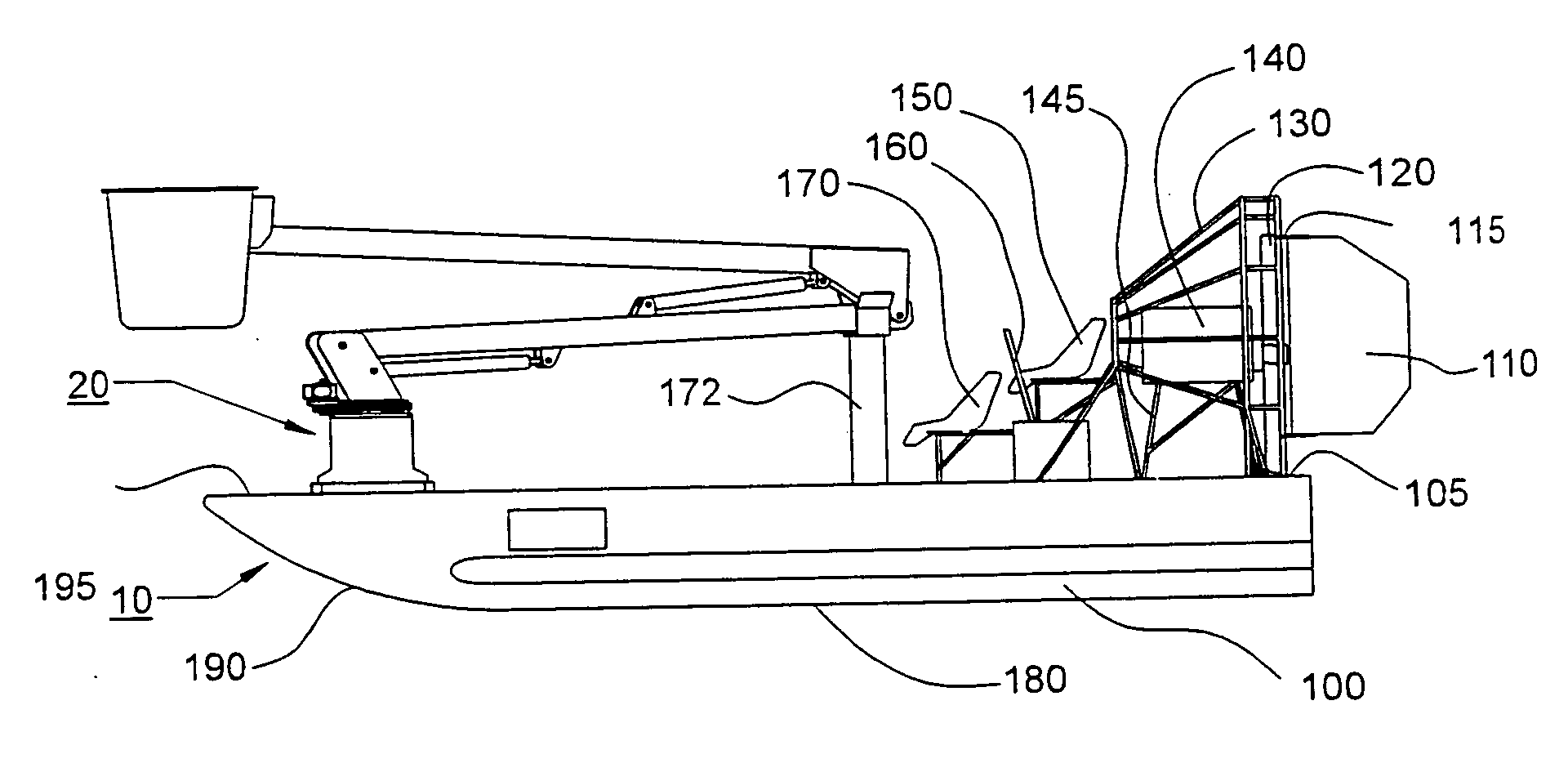
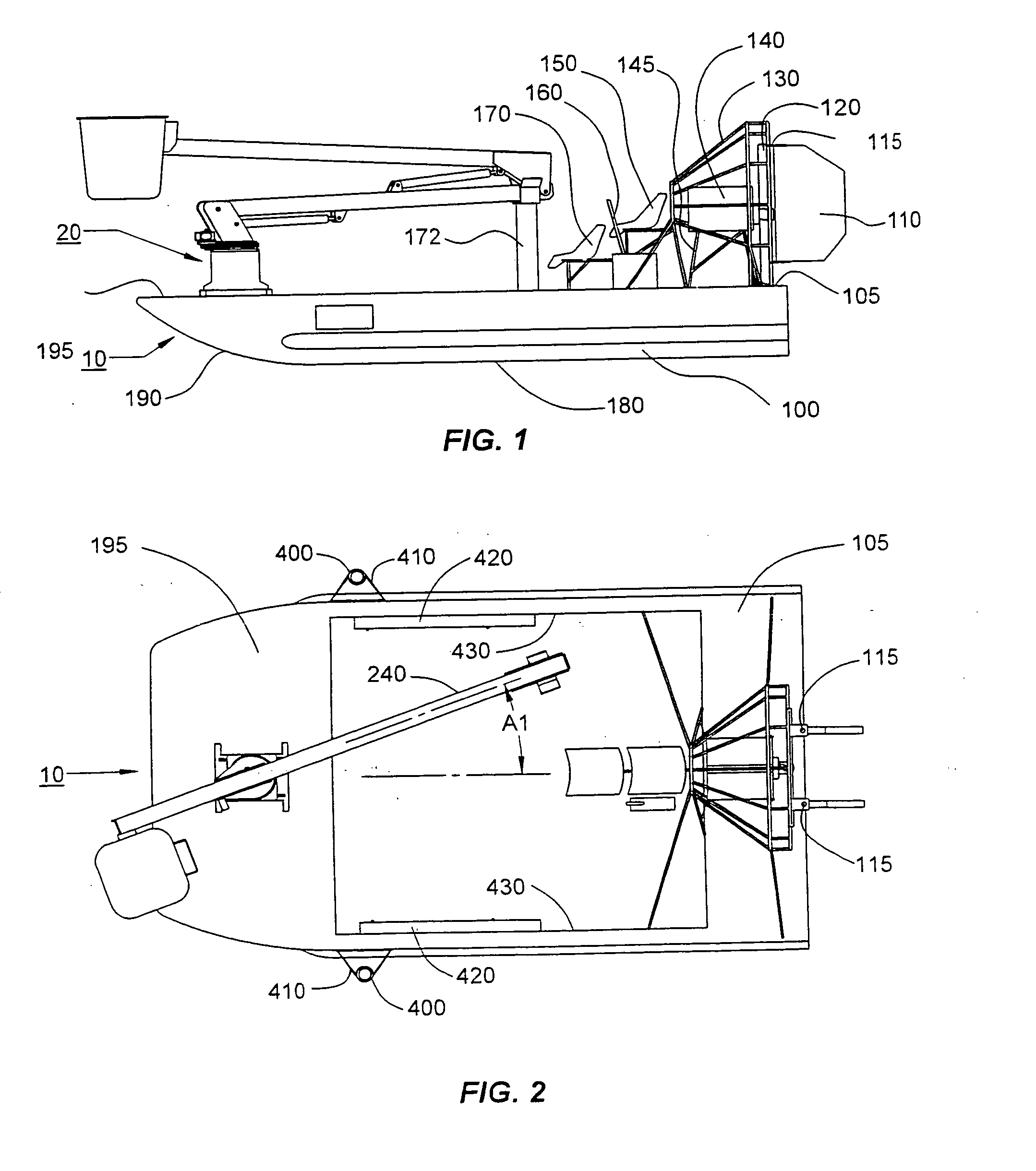
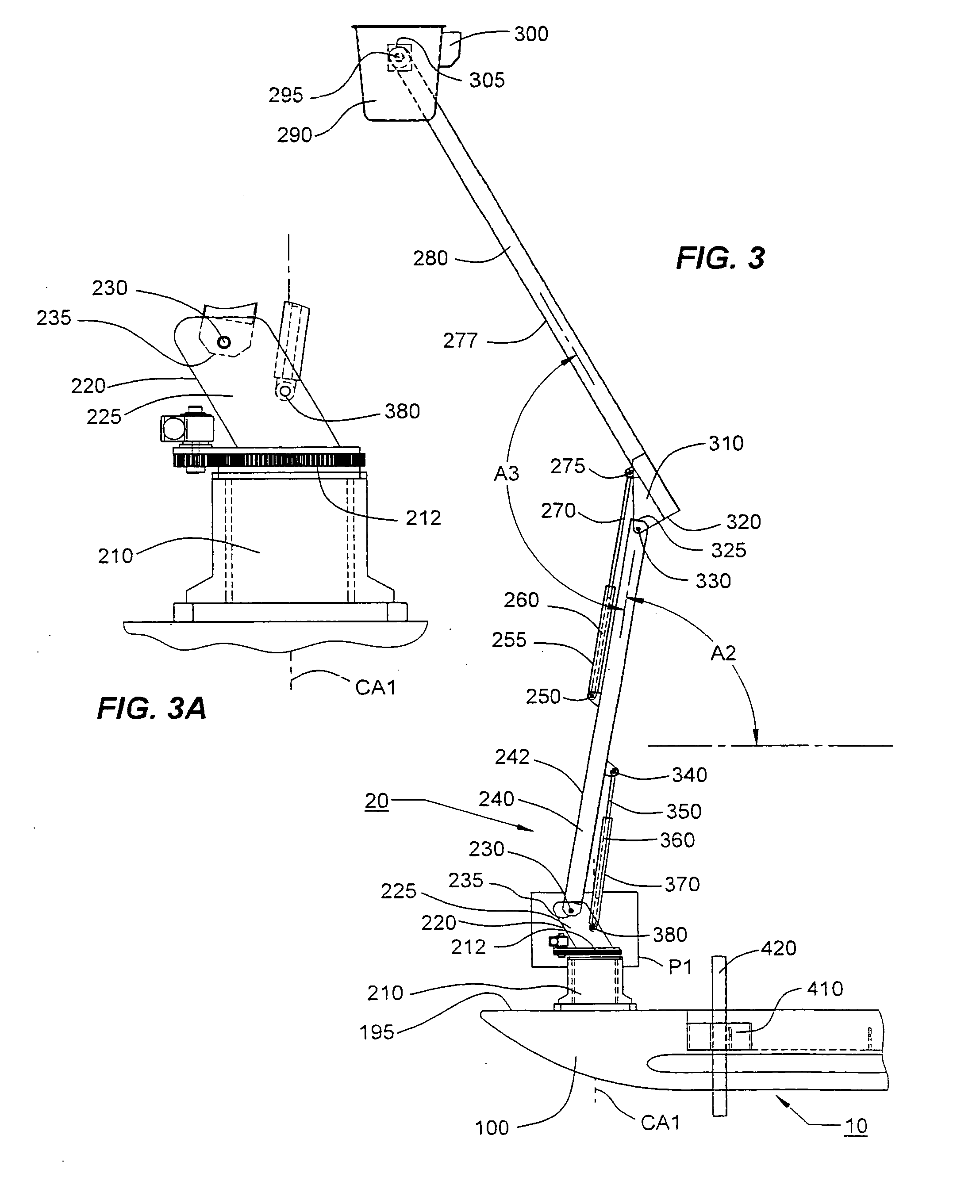
[0021]FIG. 1 depicts a side view of vessel 1 of the present invention, including air boat 10 and hydraulically operated articulating member 20. Articulating member 20 has a collapsed position depicted in FIG. 1 and FIG. 2. When air boat 10 is underway, articulating member 20 is typically maintained in said collapsed position as depicted in FIG. 1 and FIG. 2.

[0022]Air boat 10 comprises a hull 100 having a relatively flat keel 180, an aft deck 105 and a bow deck 195. Aft deck 105 and bow deck 195 are best seen in FIG. 2. Air boat 10 is powered by at least one engine 140, which in the preferred embodiment, is mounted on aft deck 105 by engine frame 145 and rotates propeller 120. In the preferred embodiment, propeller 120 is an aircraft-type propeller. Said at least one engine 140 and propeller 120 produce forward thrust by moving air rearward in a generally similar manner that an aircraft engine and an aircraft propeller produce thrust to move an airplane. Engine 140 and propeller 120 ...


PUM


Abstract

A wide, flat-bottom, buoyant, amphibious hull with a powered articulating member mounted on the deck. The hull is propelled by at least one engine-driven propeller rotating above the hull. The hull has a shallow draft and distributes its weight over a large area. These features cooperatively provide a vehicle capable of installing or servicing power transmission poles, towers, or other structures located in environmentally sensitive wetlands, swamps, marshes, shallow water, or terrain which is not efficiently accessible by other means.

Description

STATEMENTS AS TO RIGHTS TO INVENTIONS MADE UNDER FEDERALLY SPONSORED RESEARCH AND DEVELOPMENT[0001]NONEBACKGROUND OF INVENTION[0002]1. Field of Invention[0003]The present invention relates to a vessel having an articulating member. More particularly, the present invention relates to an amphibious air-propelled vessel equipped with at least one powered articulating member. More particularly still, the present invention relates to an air boat equipped with at least one powered articulating member.[0004]2. Description of Related Art[0005]Towers, such as radio transmission towers and / or electrical power transmission towers, are frequently located in shallow lakes or bays, or in low-lying, swampy or marshy wetland areas. Depending on the particular location or climate, such areas can often be covered with snow or ice.[0006]Frequently, equipment situated at or near the top of such towers requires servicing or repair. For example, it is often necessary to replace aircraft warning lights, o...

Claims


Application Information

Patent Timeline
IPC IPC(8): B63B35/30
CPCB63B27/06B63B35/00B63H7/02B63B35/44B66F11/044Y02T70/121B60F3/0007B66C23/605Y02T70/10
Inventor THIBODAUX, RONALD J.
Owner THIBODAUX RONALD J
Learn More