Fuel injection valve

a technology of fuel injection valve and valve needle, which is applied in the direction of fuel injection apparatus, fuel feed system, engine components, etc., can solve the problem that the lifting movement is no longer transmitted to the valve needle, and achieve the effect of increasing the volume of the pressure chamber

Inactive Publication Date: 2006-07-11
ROBERT BOSCH GMBH
View PDF12 Cites 31 Cited by
  • Summary
  • Abstract
  • Description
  • Claims
  • Application Information

AI Technical Summary

Benefits of technology

[0008]The fuel injector according to the present invention may provide that, given vacuum pressure in the pressure chamber, the check valve opens and releases a connection to the fuel inflow. The coupler-spring element exerts a force upon the master piston and the slave piston in an attempt to increase the volume of the pressure chamber when the coupler does not assume the maximally possible length as transmission element between the actuator and the valve needle. Due to the relatively large cross section of the inflow bore, it is then possible for fuel to continue flowing into the pressure chamber until the check valve closes at pressure parity in the pressure chamber and the fuel inflow, and the coupler assumes the maximally possible length as transmission element between the actuator and the valve needle.

Problems solved by technology

However, since gas is compressible, this lifting movement is no longer transmitted to the valve needle.

Method used


Image

  • Fuel injection valve
  • Fuel injection valve
  • Fuel injection valve

Examples


Embodiment Construction

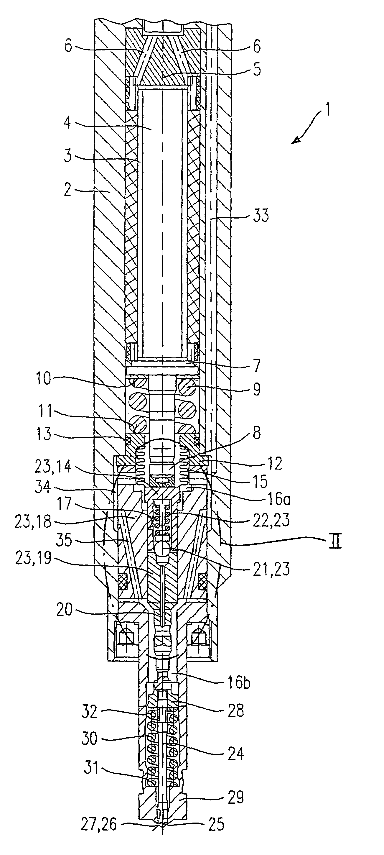
[0021]FIG. 1 shows a schematic section through an example embodiment of a fuel injector 1 configured according to the present invention. An actuator 4 is located in a valve body 2 in an actuator chamber 3, actuator 4 abutting against an actuator-support element 5. Two connecting bores 6 are used to supply electrical connecting lines for actuator 4. Actuator 4 is controlled via the connecting lines (not shown). Actuator 4 transmits its lifting movement to an actuator head 7, which is integrally formed with a tappet 8. An actuator spring 9, which abuts against a first spring system 10 of actuator head 7 and a second spring system 11 of an intermediate piece 12, exerts a prestressing force on actuator head 7, so that actuator head 7 rests against actuator 4. A sealing ring 13 seals intermediate piece 12 from valve body 2. Tappet 8 penetrates intermediate piece 12 and transmits a lifting movement of actuator 4 and actuator head 7 to a master piston 14. A corrugated tube 15 is sealingly ...


PUM


Abstract

A fuel injector, in particular a fuel injector for fuel-injection systems of internal combustion engines, including a piezoelectric or magnetostrictive actuator, actuates a valve-closure member formed on a valve needle via a hydraulic coupler, the valve-closure member cooperating with a valve-seat surface to form a valve-sealing seat. The coupler includes a master piston and a slave piston which are connected to a pressure chamber, and at least one coupler-spring element which in each instance produces a prestressing force on the master piston, counter to a working direction, and on the slave piston, in a working direction. The pressure chamber of the coupler is connected to a fuel inflow in the flow-through direction to the pressure chamber via an inflow bore and a check valve.

Description

FIELD OF THE INVENTION[0001]The present invention relates to a fuel injector.BACKGROUND INFORMATION[0002]European Patent Application No. 0 477 400 discusses a system for an adaptive, mechanical tolerance compensation, acting in the lift direction, for a path transformer of a piezoelectric actuator for a fuel injector. In this case, the actuator acts on a master (transmitter) piston connected to an hydraulic chamber, and a slave (receiving) piston, moving a mass to be driven and positioned, is moved via the pressure increase in the hydraulic chamber. This mass to be driven is, for example, a valve needle of a fuel injector. The hydraulic chamber is filled with an hydraulic fluid. When the actuator is deflected and the hydraulic fluid in the hydraulic chamber compressed, a small portion of the hydraulic fluid leaks at a defined leakage rate. In the rest phase of the actuator, this hydraulic fluid is replenished.[0003]German Published Patent Application No. 195 00 706 discusses a hydra...

Claims


Application Information

Patent Timeline
Patent Type & Authority Patents(United States)
IPC IPC(8): B05B1/08F02M51/06F02M61/08F02M61/16
CPCF02M51/0603F02M61/167F02M61/08F02M2200/21
Inventor HAAG, GOTTLOBHUEBEL, MICHAELSTEIN, JUERGEN
Owner ROBERT BOSCH GMBH
Why Eureka
Try Eureka