
Connector assembly

a technology of connecting parts and connectors, applied in the direction of coupling device connections, coupling protective earth/shielding arrangements, two-part coupling devices, etc., can solve the problems of inability to achieve perfect transmission, and high cost of perfect electrical shields, etc., to achieve easy detachability and simplify the effect of parts assembling to each other

Inactive Publication Date: 2006-07-11
HON HAI PRECISION IND CO LTD
View PDF15 Cites 19 Cited by
  • Summary
  • Abstract
  • Description
  • Claims
  • Application Information

AI Technical Summary

Benefits of technology

[0008]Therefore, an object of the present invention is to provide a connector assembly having simplified parts to assemble to each other and be detachable easily.
[0009]Another object of the present invention is to provide a connector assembly that can be fitted together very conveniently and quickly to shorten and simplify the manufacturing process for timesaving and cost down.
[0010]Another object of the present invention is to provide a connector assembly with a large number of necessary integrated components which is accessible to rework or repair by detaching them easily rather than costly disposal of the whole connector assembly.
[0011]The other object of the present invention is to provide a multi-port connector assembly with each mating port having their own integral components. These components can be integrated to assemble and affix to the connector assembly by easily fixing attachment.
[0012]A further object of the present invention is to provide same parts which can be used for at least two kinds of the connector assembly having a different number of mating ports from others and is not in need of producing any additional new parts for another new port-numbered application.
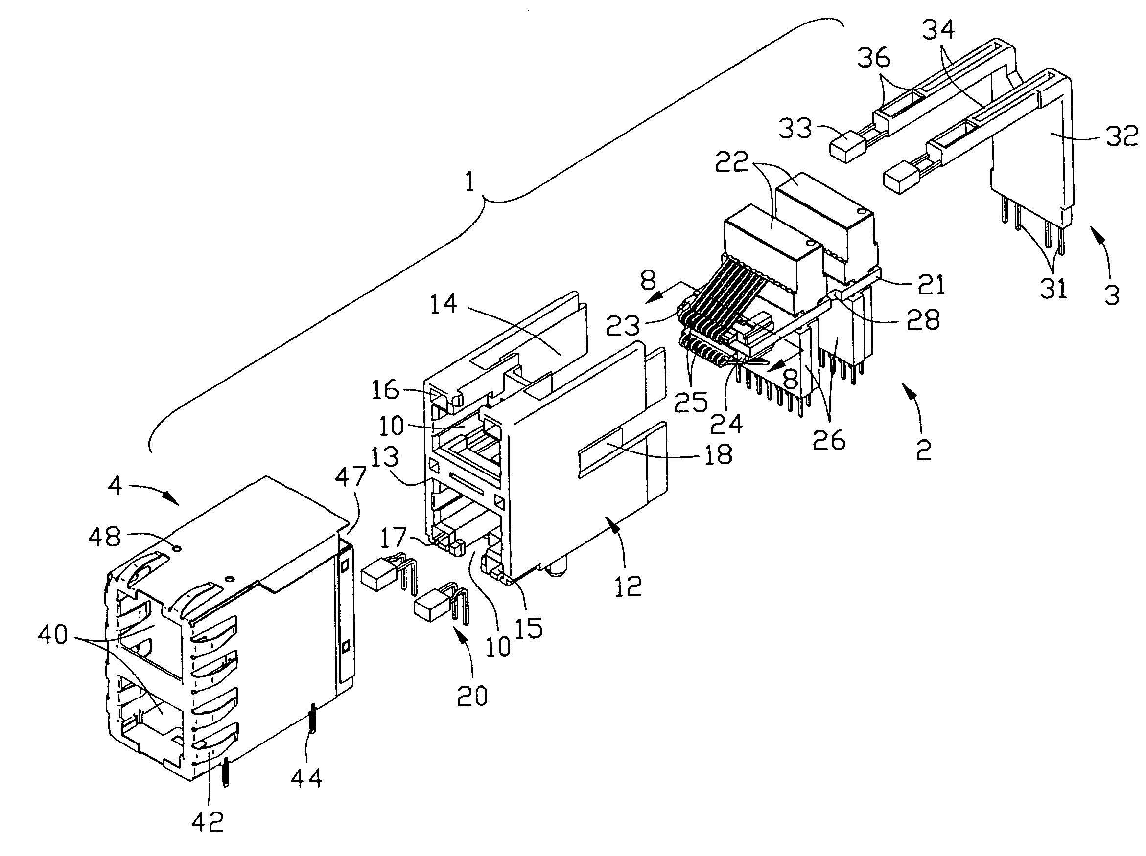
[0014]Specifically, at least one flexible latch is formed on the middle portion of one sidewall of the housing. At one edge of the circuit board, a notch is formed corresponding to the latch of the housing. When assembling, the conditioning unit is inserted into the housing and the edge of the circuit board is snug in a guiding groove formed on the inward side of the sidewall and the latch is then engaged with its corresponding notch to fix the unit in position. For such an arrangement, the conditional unit is easily secured to the housing and finally settled between two mating ports to ease the assembly of two terminal modules for each mating port. And the latch is easily detached from the notch of the circuit board by hands or a tool to simplify any rework or repair process.

Problems solved by technology

Usually the signals transmitted by cables are easily affected because of the diversity and unpredictability of the environment cables meet.
However, in high frequency and speed situation, any necessary connection is always a deficiency to cause signals interfered by an outer noise source and failing to achieve the perfect transmission.
And the cost for a perfect electrical shield is expensive too.
However, to use wires of the coil as contactors of the modular jack connector cause more complicated assembling process always costs high and is time-consuming.
It is obviously laborsaving because the contactors of the connector are mounted to the printed board after the filter circuit and related electronic elements are mounted onto the printed board in advance.
The method adopted in Loudermilk et al. needs to be improved due to the expensive cost to produce its built-in printed board and still complicated process to assemble the printed board and the connector housing.
And in the multi-port application, the increasing contactors need to be mounted onto the motherboard will make it much more difficult to dispose or assemble the built-in printed board.
However, much more procedures are needed to manufacture the subassembly and most of them like insert-molded parts cost expensively.
However, in this case, too many parts are needed and the assembling process is still complicated and labor consuming.
In conclusion, it is understandable that most of methods adopted by these prior arts mentioned above have a complicated process, especially when assembling.
Meanwhile, it is difficult to dismantle parts if some of them fail to work.
Some of parts disclosed in prior art are vulnerable when removing from the housing.
That means it is impossible to rework or repair on them if some of them need to change.
Furthermore, no parts in prior art can be used in another product applications having a different number of mating ports.

Method used


Image

  • Connector assembly
  • Connector assembly
  • Connector assembly

Examples


first embodiment

[0034]Referring to FIG. 9, an unshielded subassembly 6 of a connector assembly with multi ports is shown. An integral unshielded housing 60 is formed to put all ports together in two-rowed side-by-side arrangement. A conditioning unit 61 with a common circuit board 63 is inserted into a mutual receiving space (not shown) in the rear portion of the housing 60 by having two opposite side edges of the circuit board 61 snug in two guiding grooves (not shown) formed on the inward side of the sidewall of the housing 60. A flexible latch 62 is formed on the middle portion of every sidewall of the housing 60 and can be engaged with a corresponding notch 65 formed on a side edge of the circuit board 63. A magnetic filtering / conditioning component set 66 and tail module 67 corresponding to each of the mating ports are surface mounted on the upper and lower sides of the circuit board 63 respectively. Pairs of Terminal modules 68 each has two modules to be inversely surface mounted on the two s...

third embodiment

[0035]Referring to FIG. 10, a third embodiment in accordance with the present invention is suggested to provide a single mating port of a module jack 7. Same parts used for the former embodiment can be adopted again to make the conditioning unit 71 of this modular jack 7. Two latches 72 are formed on the unshielded housing 70 of this modular jack 7 and are engaged with a notch 73 formed on the edge of the conditioning unit 71 to position it.

[0036]Referring to FIGS. 11 and 13 a subassembly 8 of a connector assembly with multi ports in another embodiment is shown. The subassembly 8 comprises a signal conditioning circuit board 81 having a plurality of resistors and inductors (not labeled) mounted thereon, an integral first and second circuit boards 82, 83 carried a plurality of first and second terminal sets 821, 831, and a plurality of separately conditioning units 84. Each conditioning unit 84 has a pair of magnetic modules 841 and a middle grounding shell 85 arranged between the ma...


PUM


Abstract

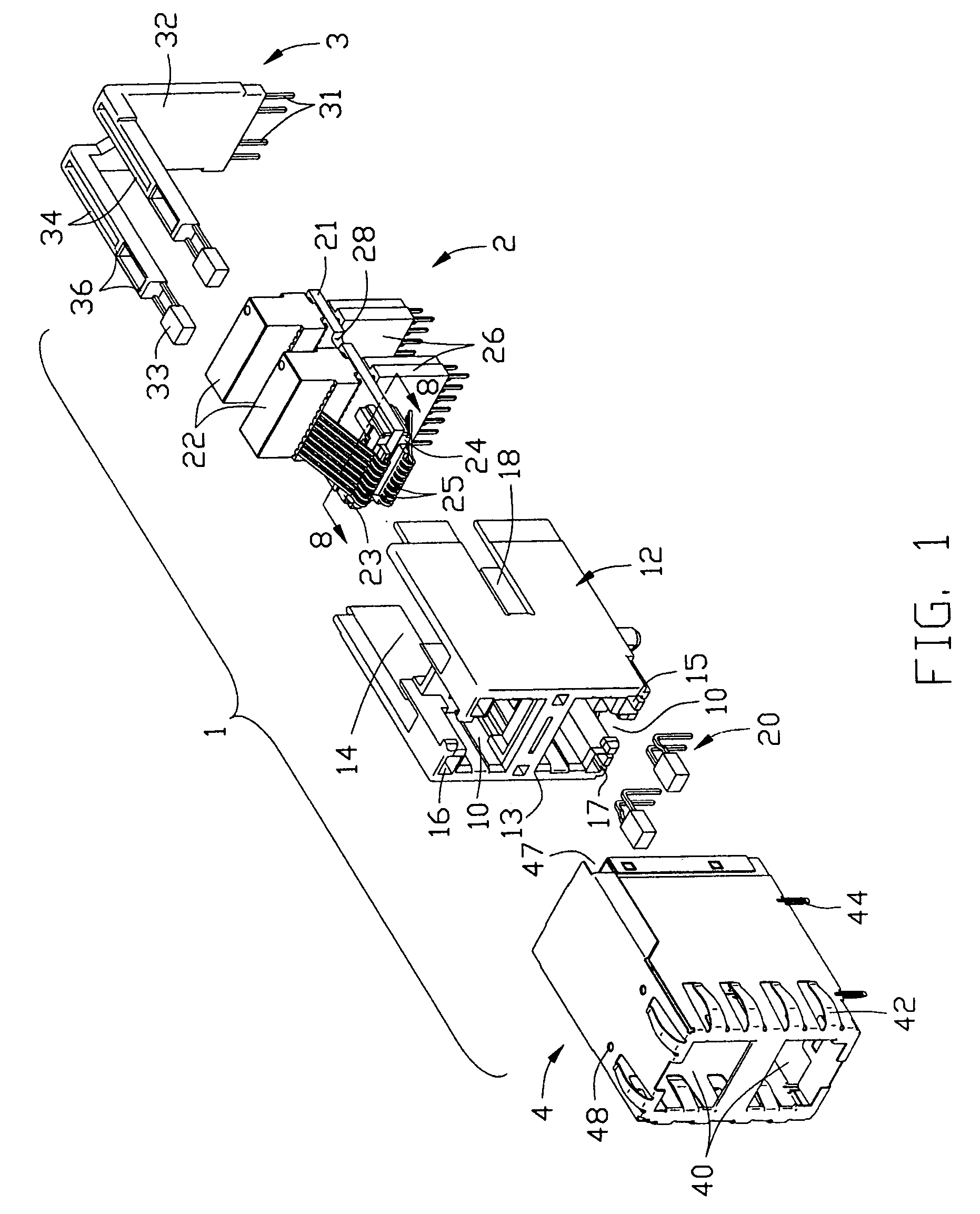
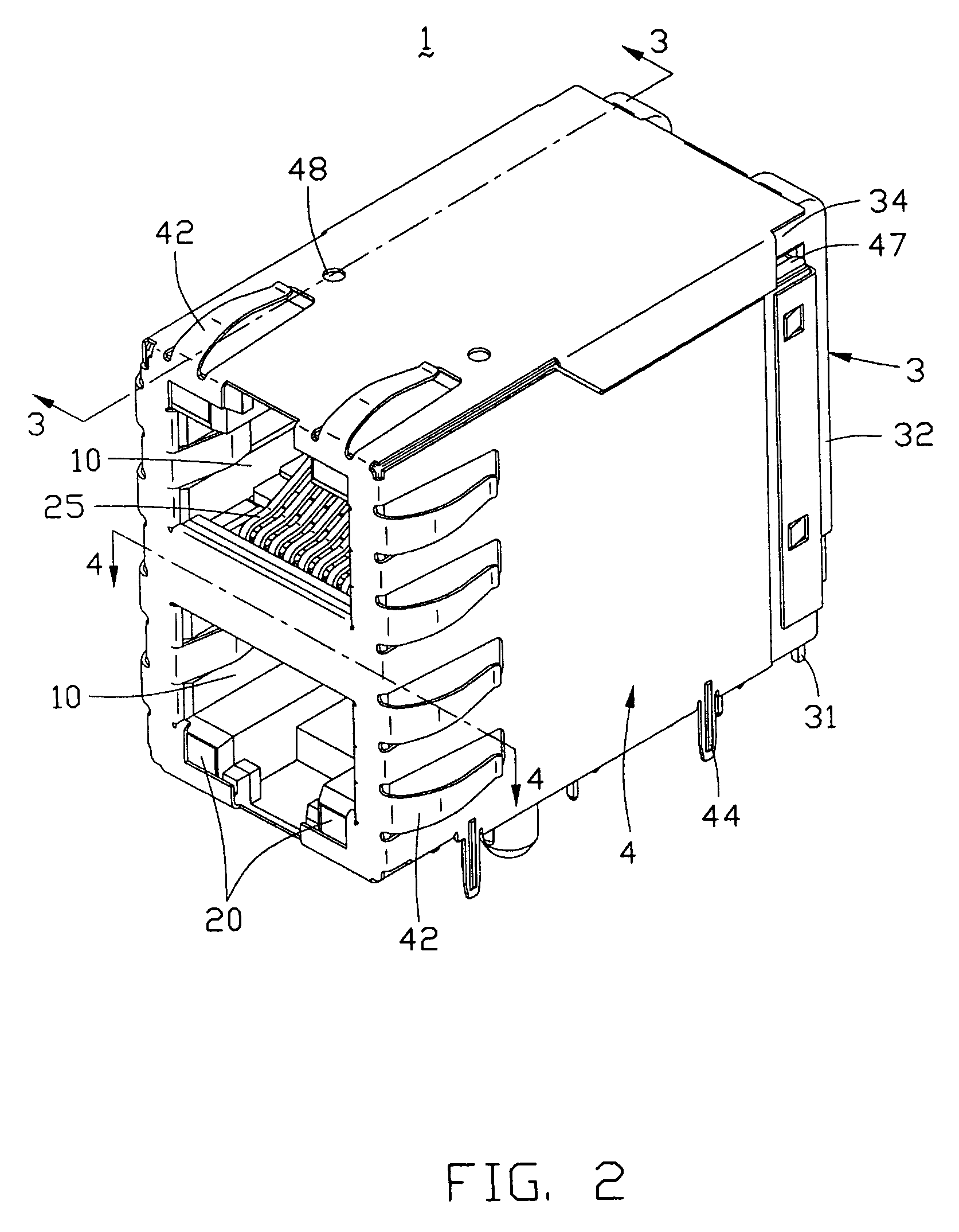
A connector assembly (1) mounted on a printed circuit board for mating with the network cable includes a housing (12) configured to form two mating ports (10) for receiving their complementary connectors. A conditioning unit (2) is mounted into the housing (12) to be disposed between the mating ports (10), and includes a common circuit board (21) having conditioning components (22) and two terminal modules (23, 24) surface mounted thereon. Each of the terminal modules (23, 24) has terminals (25) insert-molded therein and is mounted on a different side of the circuit board (21) from each other. At least one flexible latch (18) is formed on the middle portion of a sidewall of the housing (12) and a notch (28) is formed at one edge of the circuit board (21) to be engaged with the latch (18) to fix the conditioning unit (2) in position. Thus, the conditional unit (2) is easily secured to the housing and the latch (18) is easily detached from the notch (28) by a tool.

Description

CROSS-REFERENCE TO RELATED APPLICATION[0001]This patent application is related to U.S. patent application Ser. No. 10 / 036,073, filed on Oct. 19, 2001, entitled “CONNECTOR ASSEMBLY”, now U.S. Pat. No. 6,709,295 having the same assignee with the instant application.BACKGROUND OF THE INVENTION[0002]1. Field of the Invention[0003]The present invention is related to a connector assembly of modular jacks, especially to a connector assembly having a conditioning unit including a circuit board with magnetic filter / conditioning components mounted on it to condition the signals passing through them.[0004]2. Description of the Related Art[0005]The communication between computers becomes more and more important because of the prevalence of the Internet. People use the Internet or an internal network everyday for their daily work, entertainment, and other personal affairs. However, for each of personal computers or end-user terminals, a mutual intermediary like cables or wires is necessary to co...

Claims


Application Information

Patent Timeline
Patent Type & Authority Patents(United States)
IPC IPC(8): H01R13/648H01R13/60H01R13/66H01R13/717
CPCH01R13/6658H01R13/7175H01R13/717H01R24/64H01R25/006
Inventor HYLAND, JAMES H.
Owner HON HAI PRECISION IND CO LTD
Learn More