Convertible mode vascular catheter system

a vascular catheter and avertible mode technology, applied in the field of vascular catheters, can solve the problems of affecting the service life of the catheter, the inability to permit the ready exchange of guidewires, and the damage of the guidewire tip

Inactive Publication Date: 2006-07-11
ABBOTT CARDIOVASCULAR
View PDF76 Cites 68 Cited by
  • Summary
  • Abstract
  • Description
  • Claims
  • Application Information

AI Technical Summary

Problems solved by technology

If the balloon size and diameter is smaller than the native artery, the results of balloon angioplasty are suboptimal, requiring a second dilation with a larger-sized balloon, and if balloon size is too large for the native artery, complications may occur due to arterial wall damage.
However, this catheter has a serious drawback of not being able to permit ready exchange of guidewires.
During angioplasty procedures, the guidewire tip may become damaged, may be needed of a different type of guidewire or may need to be reshaped to complement the patient's vasculature.
However, with the rapid-exchange type catheter of U.S. Pat. No. 4,762,129, guidewire exchange requires complete removal and reinsertion of both the guidewire and the angioplasty catheter; thus, defeating the original goal of expedient advantage of the rapid-exchange catheter.
Another disadvantage of the rapid-exchange catheter is backbleeding.

Method used


Image

  • Convertible mode vascular catheter system
  • Convertible mode vascular catheter system
  • Convertible mode vascular catheter system

Examples


Embodiment Construction

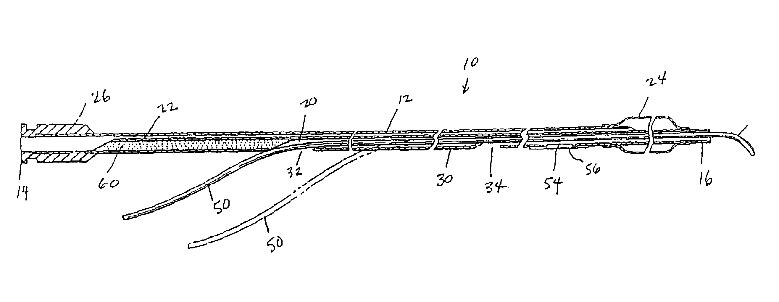
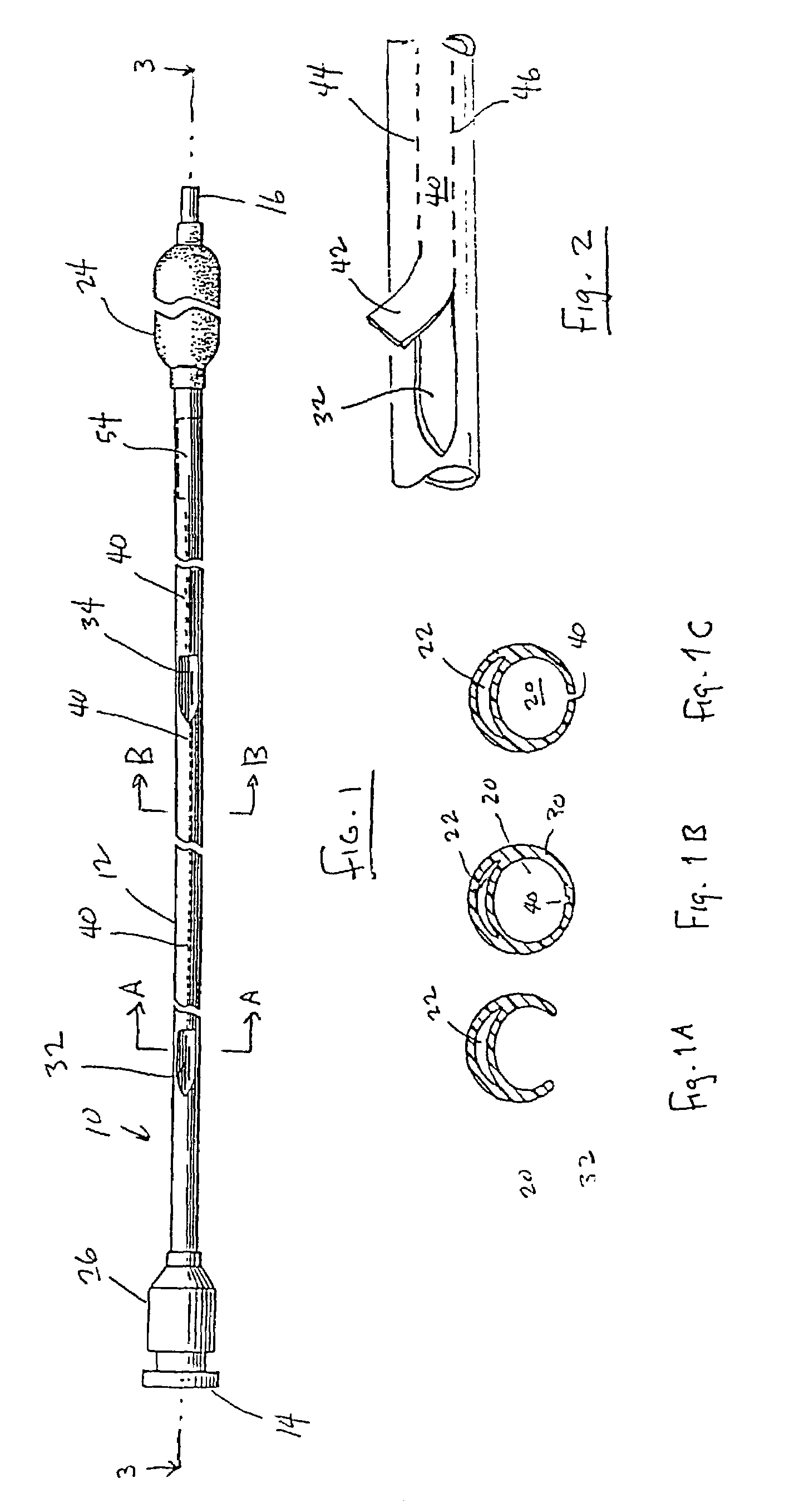
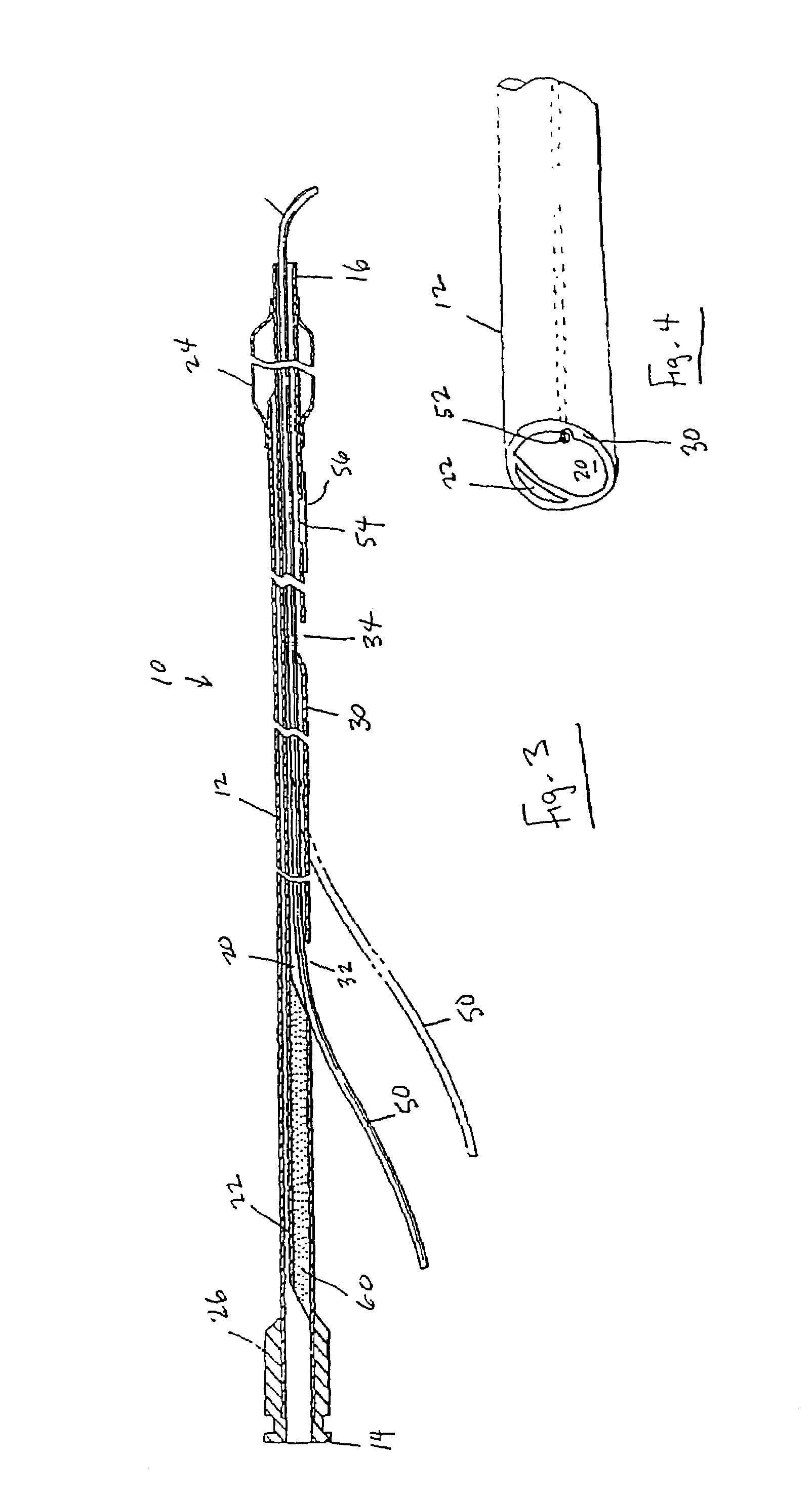
[0036]A basic embodiment of the catheter of the present invention is illustrated in FIG. 1. A catheter 10 is provided with a catheter shaft 12 extending from a proximal end 14 to a distal end 16. As shown more clearly in FIG. 1B, the interior of the catheter shaft 12 has a guidewire lumen 20 and a balloon inflation lumen 22 extending through the catheter shaft 12.

[0037]The catheter 10 has an angioplasty balloon 24 at the distal end 16 thereof. At the proximal end 14 of the catheter shaft 12, a balloon inflation connector 26 is provided in fluid communication with the balloon lumen 22. Fluid introduced into the proximal end of the balloon inflation connector 26 can travel through the balloon lumen 22 and into the interior of the balloon 24 to inflate and deflate the balloon 24 during an angioplasty procedure. The balloon inflation lumen 22 terminates inside the balloon 24. The opposite end of the balloon inflation lumen 22 terminates inside the balloon inflation connector 26.

[0038]Th...


PUM


Abstract

An angioplasty catheter comprising a catheter shaft having a proximal portion and a distal end, an angioplasty balloon attached to the shaft at the distal end, a balloon inflation lumen extending through the shaft and communicating with the interior of the balloon, a guidewire lumen extending through the shaft and through the balloon for receiving a steerable guidewire, the guidewire lumen having an outside wall, wherein the guidewire lumen has a proximal opening located at a point normally outside of the patient during use of the catheter for insertion of a guidewire into the lumen, and a side port adapted to permit passage of a guidewire into the lumen through the outside wall of the guidewire lumen, the side port located distally of the proximal opening and at a point normally inside of the patient during use, and guidewire removing means in the outside wall of the guidewire lumen extending from the proximal opening to the side port for permitting a guidewire in the guidewire lumen to be moved laterally from the guidewire lumen through the outside wall of the guidewire lumen. Also disclosed are a removable “Y” connector and methods for using the catheter and for exchanging catheters and guidewires during vascular catheterization procedures.

Description

RELATED APPLICATIONS[0001]This application is a continuation of application Ser. No. 07 / 714,642 filed Jun. 13, 1991 now U.S. Pat. No. 6,824,554, the disclosure of which is hereby incorporated by reference in its entirety.BACKGROUND OF THE INVENTION[0002]This invention relates to vascular catheters (such as angioplasty catheters) specially adapted for rapid-exchange of both the guidewire and the catheter during use. It also relates to the method of using those catheters.[0003]Percutaneous transluminal coronary angioplasty (PTCA) has emerged as the major viable present alternative to bypass surgery for revascularization of stenotic and occluded coronary arteries. Although transluminal angioplasty has application in peripheral artery disease, it is most widely used in the treatment of coronary artery disease. Unlike bypass surgery, percutaneous angioplasty does not require general anesthesia, cutting of the chest wall, extracorporeal perfusion, or transfusion of blood. Percutaneous cor...

Claims


Application Information

Patent Timeline
Patent Type & Authority Patents(United States)
IPC IPC(8): A61M29/00A61M29/02
CPCA61M25/104A61M2025/0063A61M2025/0098A61M2025/0183A61M2025/107A61M2025/0034A61M25/0029A61M25/0032A61M25/007A61M25/0023
Inventor JANG, G. DAVID
Owner ABBOTT CARDIOVASCULAR
Why Eureka
Try Eureka