Multiple-hole terminal lug, bussing assembly and electrical switching apparatus including the same

a terminal lug and multi-hole technology, applied in the direction of contact, switchgear with a retractable carriage, connection contact material, etc., can solve the problems of longstanding difficulty in the electrical switching apparatus art in regard to being able to provide desired or required electrical connections, and inconvenient to use, so as to reduce the amount of space required and increase the number of electrical cables

Inactive Publication Date: 2006-07-11
EATON CORP
View PDF10 Cites 19 Cited by
  • Summary
  • Abstract
  • Description
  • Claims
  • Application Information

AI Technical Summary

Benefits of technology

[0010]These needs, and others, are met by the present invention which provides a multiple-hole terminal lug for electrical switching apparatus. The terminal lug couples directly to a terminal extension or runback, thereby eliminating the need for a separate riser adapter. The terminal lug may include a plurality of receptacles for receiving a corresponding plurality of electrical connection mechanisms (e.g., without limitation, cables; wires) and also has the ability to be electrically coupled to the runback in a variety of orientations (i.e., sloped upward or downward) thus increasing the number of electrical cables and thus the load which may be employed while reducing the amount of space required therefor.
[0014]The first mounting holes in the terminal extension may include two or more primary mounting holes, the second mounting holes in the mounting portion may include three or more secondary mounting holes and the at least one first fastener may include two or more first fasteners wherein at least two of the three or more secondary mounting holes in the mounting portion align with at least two of the two or more primary mounting holes in the terminal extension in order to receive the two or more first fasteners therein thereby securing the multiple-hole terminal lug in one of the first and second mounting configurations.

Problems solved by technology

This makes attaching electrical cables, for example, to the load terminals difficult.
In view of the foregoing, there is a well known, longstanding difficulty in the electrical switching apparatus art with regard to being able to provide desired or required electrical connections within confined spaces.
However, such a design is limited by the number of standard one-cable lugs 14 that can be mounted upon the risers 10 (e.g., four lugs 14 are mounted on each riser 10 in FIG. 1).

Method used


Image

  • Multiple-hole terminal lug, bussing assembly and electrical switching apparatus including the same
  • Multiple-hole terminal lug, bussing assembly and electrical switching apparatus including the same
  • Multiple-hole terminal lug, bussing assembly and electrical switching apparatus including the same

Examples


Embodiment Construction

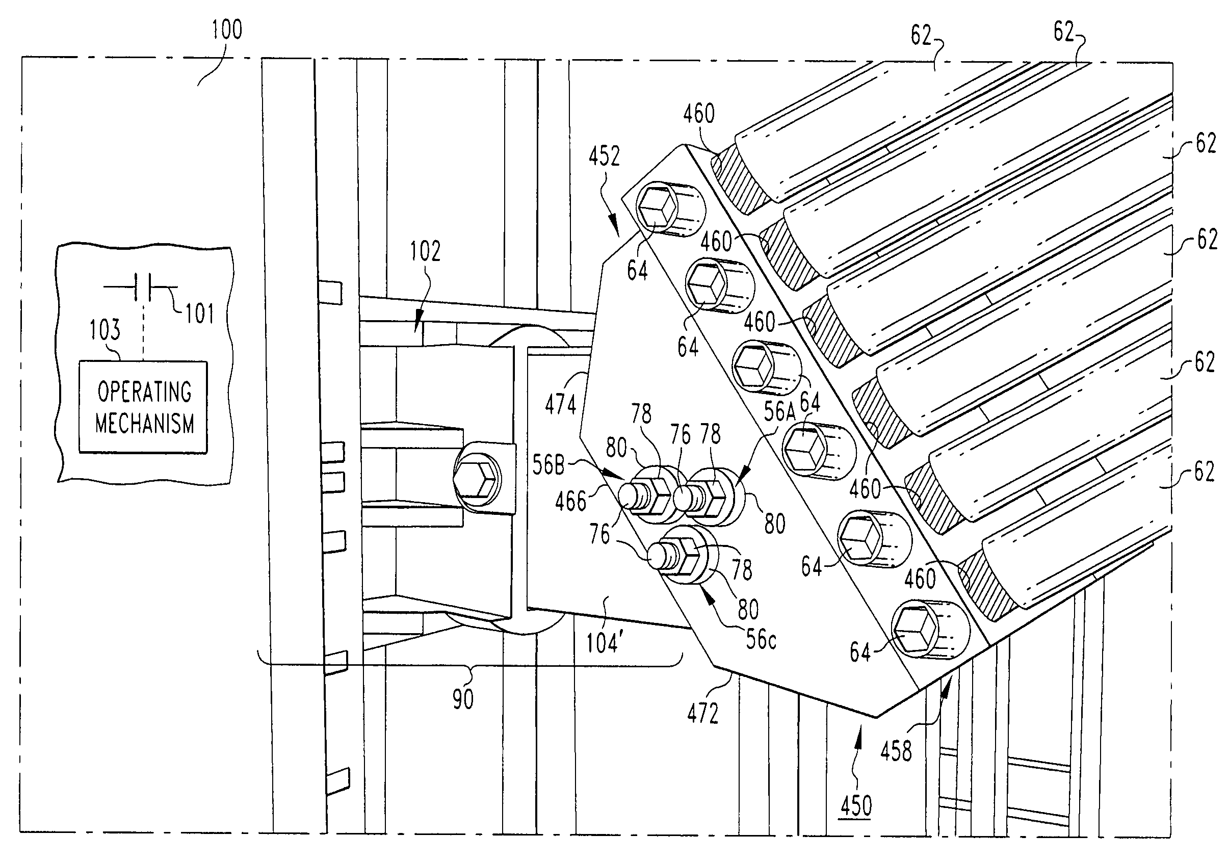
[0024]For purposes of illustration, the invention will be described as applied to terminal lugs for receiving a plurality of cables at the terminations (e.g., load terminals) of a low voltage circuit breaker, although it will become apparent that it could also be applied to other types of circuit breakers and to other types of electrical switching apparatus (e.g., without limitation, circuit switching devices and other circuit interrupters such as contactors, motor starters, motor controllers and other load controllers having one or more line or load terminals). It will also be appreciated that, for ease of illustration, the invention is described and illustrated herein as employed on one terminal of one pole of a low voltage circuit breaker. However, the invention is also for terminals of circuit breakers having any number of poles (i.e., multi-pole circuit breakers).

[0025]Directional phrases used herein, such as, for example, upper, lower, front, back and derivatives thereof, rela...


PUM


Abstract

A multiple-hole terminal lug is for a circuit breaker including a load terminal and a conductive terminal extension coupled thereto. The multiple-hole terminal lug includes a mounting portion and a receiving portion having a plurality of receptacles for electrically coupling a corresponding plurality of electrical cables to the load terminal. Secondary mounting holes in the mounting portion align with primary mounting holes in the terminal extension in order to receive fasteners therein and secure the multiple-hole terminal lug in a first or second mounting configuration sloping upward or downward with respect tot the longitudinal axis of the terminal extension.

Description

BACKGROUND OF THE INVENTION[0001]1. Field of the Invention[0002]The present invention relates generally to electrical switching apparatus and, more particularly, to terminations, such as terminals, for a circuit breaker.[0003]2. Background Information[0004]Electrical switching apparatus include, for example, circuit switching devices and circuit interrupters such as circuit breakers, contactors, motor starters, motor controllers and other load controllers.[0005]Low voltage circuit breakers, for example, which are used in power distribution systems, are commonly mounted, either alone or in combination with additional switchgear, within a housing (e.g., without limitation, a load center). Frequently, the load side of the circuit breaker and the terminals thereof are disposed in the back of such housing thus providing very little space for accessing the circuit breaker load terminals. This makes attaching electrical cables, for example, to the load terminals difficult. Adding to this d...

Claims


Application Information

Patent Timeline
Patent Type & Authority Patents(United States)
IPC IPC(8): H02G5/00H01H1/58H01H1/64H01H11/00
CPCH01H1/5855H01H11/0031H01H2011/0037
Inventor ROWE, NEAL E.ABRAHAMSEN, MICHAEL H.MOORE, STANLEY E.FAIR, TIMOTHYSCOTT, MARLYCE J.
Owner EATON CORP
Why Eureka
Try Eureka