Apparatus and method for non-destructive inspection

a non-destructive inspection and inspection apparatus technology, applied in the direction of reradiation, electromagnetic wave detection, instruments, etc., can solve the problems of large difference in the diagnosis result between inspectors, low reliability in detecting and diagnosing defects, cracks and cavities, etc., and achieves short time, high reliability, and high accuracy

Inactive Publication Date: 2006-07-11
MITSUBISHI HEAVY IND LTD
View PDF8 Cites 22 Cited by
  • Summary
  • Abstract
  • Description
  • Claims
  • Application Information

AI Technical Summary

Benefits of technology

[0012]Therefore, an object of the present invention is to provide a non-destructive inspection apparatus and method which uses an electromagnetic wave and carries out the inspection of defects in a target structure in a short time with a high accuracy and a high reliability.
[0019]Also, the pattern matching section may introduce a weight on at least one part of the waveform of the received wave signal to decrease the effect from the received wave signal from a surface of the inspection target.
[0033]In order to carry out the optimal pattern matching between the waveform of the actual received wave signal and the waveform of the predicted wave signal represented as a linear combination of the fundamental reflected wave signals, it is necessary to optimize the linear combination coefficients and the round propagation times of the respective fundamental reflected waves. However, if the pattern matching is carried out with all the linear combination coefficients and the round propagation times as variables for the optimization, this is not practical since there is a risk of falling in a local minimum around a true one and a vast time is required for the optimization. For these reasons, the linear combination coefficients are analytically determined, whereas the round propagation times of the fundamental reflected waves are determined numerically by shifting the times. Thus, the local minimum is avoided and the computation time is extremely reduced.

Problems solved by technology

However, in this hammering test method, the reliability in detecting and diagnosing the defects, such as cracks and cavities, is low, and a difference in the diagnosis result between inspectors is large.
Also, it is that a consecutively inspectable time is limited to about 30 minutes.
Thus, the hammering test method is an inspection method whose load on the inspector is extremely heavy.
However, the detection of the crack is difficult in the case of an inspection target with no sunshine, such as inside a tunnel.
In addition, the method takes a long time for inspection and only a crack existing in a place less than 5 mm deep from the surface can be detected.
In the X-ray method, the treatment of the apparatus used in the inspection is not only troublesome, but also only a qualified person can carry out the inspection.
In addition, a risk is involved and a cost of the inspection becomes expensive.
Furthermore, the method cannot be applied to a structure, such as a tunnel, where the diagnosis must be carried out only from one side.
However, it is difficult to detect the first reflected wave, and consequently to measure the round propagation time, since a composite wave of strongly superposed multi-reflected waves is observed by the ultrasonic sensor.
Consequently, it takes an extremely long time to carry out the inspection for a tunnel or the like, although there is no problem in its use for a case where an inspection target is small.
Thus, an excellent result is hardly obtained.

Method used


Image

  • Apparatus and method for non-destructive inspection
  • Apparatus and method for non-destructive inspection
  • Apparatus and method for non-destructive inspection

Examples


Embodiment Construction

[0041]Hereinafter, a non-destructive inspection apparatus of the present invention will be described below in detail with reference to the attached drawings. In the following description, a concrete structure is exemplified as an inspection target. However, it could be understood to a person skilled in the art that the inspection target is not limited to the concrete structure.

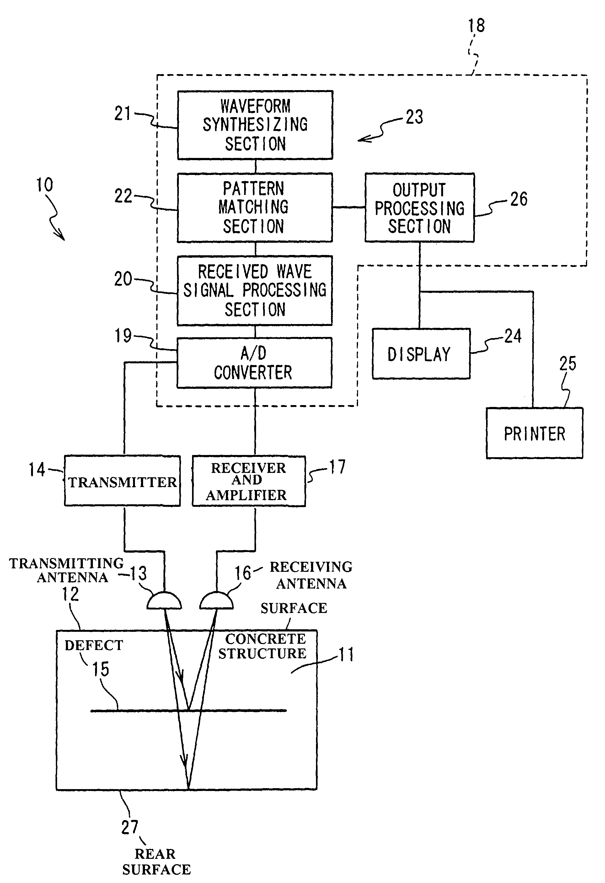
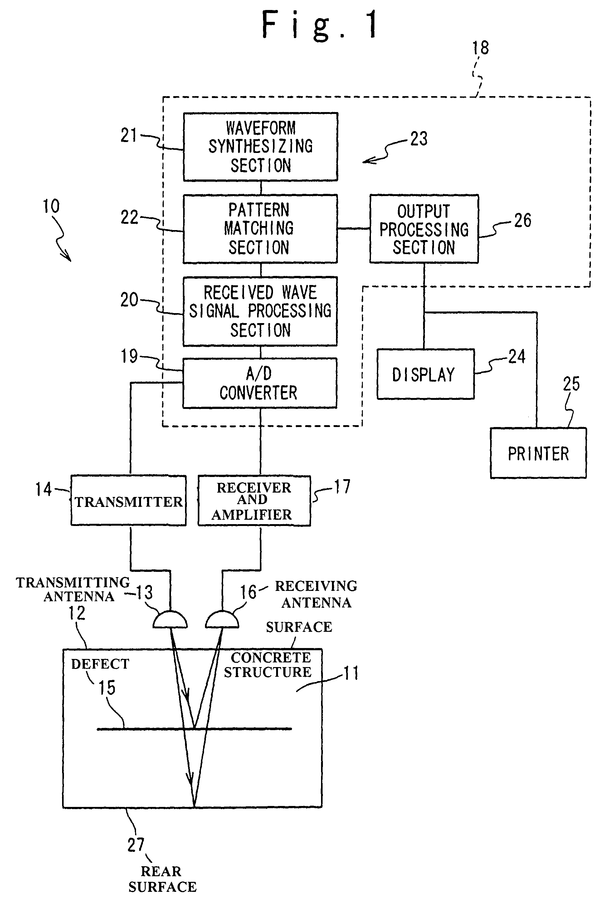
[0042]FIG. 1 is a block diagram showing the non-destructive inspection apparatus according to the present invention. Referring to FIG. 1, the non-destructive inspection apparatus 10 of the present invention is composed of a transmitting antenna 13, a transmitter 14, a receiving antenna 16, and a receiver and amplifier 17. The transmitting antenna 13 is faced to the surface 12 of a concrete structure 11, and the transmitter 14 transmits an electromagnetic wave signal to the concrete structure 11. The receiving antenna 16 is faced to the surface 12 of the concrete structure 11, and receives reflected electromagn...


PUM

PropertyMeasurementUnit
thicknessaaaaaaaaaa
distanceaaaaaaaaaa
propagation velocitiesaaaaaaaaaa

Abstract

A non-destructive inspection apparatus includes a transmitting section, a reception section and a processing unit. The transmission section irradiates an electromagnetic wave signal toward an inspection target. The reception section receives a reflected electromagnetic wave signal from the inspection target to generate a received wave signal. The processing unit generates a fundamental reflected wave signal predicted to be received from each reflection point of the inspection target, and determines the existence or nonexistence of any defects in the inspection target and the details of the defect, if it exists, based on a pattern matching between a waveform of the received wave signal and a waveform of a linear combination of fundamental reflected wave signals.

Description

BACKGROUND OF THE INVENTION[0001]1. Field of the Invention[0002]The present invention relates to a non-destructive inspection apparatus and method for inspecting a target structure.[0003]2. Description of the Related Art[0004]Conventionally, there are known non-destructive inspection methods of detecting a defect, such as a crack and a cavity, in a concrete structure, such as a tunnel and a bridge. As one of the non-destructive inspection methods, a so-called hammering test method is known.[0005]In the hammering test method, the defect is detected from a reaction, a tone and the like brought about when a skilled inspector makes an impact on the concrete structure with a hammer. However, in this hammering test method, the reliability in detecting and diagnosing the defects, such as cracks and cavities, is low, and a difference in the diagnosis result between inspectors is large. Also, it is that a consecutively inspectable time is limited to about 30 minutes. Thus, the hammering test...

Claims


Application Information

Patent Timeline
Patent Type & Authority Patents(United States)
IPC IPC(8): G01R27/32G01V3/12G01N21/95G01N22/00G01N22/02G01N33/38G01S13/10
CPCG01N21/95G01N33/383G01N22/02
Inventor TANAKA, SHOGO
Owner MITSUBISHI HEAVY IND LTD
Why Eureka
Try Eureka