Motor protector particularly useful with hermetic electromotive compressors

a technology of electromotive compressors and motor protectors, which is applied in the direction of machines/engines, liquid fuel engines, positive displacement liquid engines, etc., can solve the problems of reducing the difference between the operating current during normal or rated operation and the constrained current which occurs during abnormal operation, and the amount of heat generated can be large, so as to improve the operating efficiency of equipmen

Active Publication Date: 2006-07-11
SENSATA TECH MASSACHUSETTS INC
View PDF25 Cites 30 Cited by
  • Summary
  • Abstract
  • Description
  • Claims
  • Application Information

AI Technical Summary

Benefits of technology

[0007]An object of the invention is the provision of a protector which overcomes the limitations noted above and to improve the operating efficiency of the equipment that is to be protected. Another object of the invention is the provision of a protector which is capable of minimizing the difference between the rated operating current and the constrained operating current of the equipment to be protected. Yet another object of the invention is the provision of a protector in which actuation of snap action of the bimetal disc is accurately controlled. Still another object of the invention is a protector that incorporates an improvement over conventional protectors for hermetic type electromotive compressors.
[0008]According to the invention, a protector made according to the invention comprises a metal header that secures a first and a second terminal in electrically insulated relationship with one another, a metal housing secured to the header so as to form a chamber, a stationary contact disposed within the chamber which is electrically connected to the first terminal, a heater disposed within the chamber that is electrically connected to the second terminal in such a fashion as to form a current path between the second terminal and the header and an arm assembly which is arranged in the chamber and having an end thereof secured to the housing. The arm assembly includes an electrically conductive movable plate including a movable contact adapted to engage the stationary contact, a thermally responsive, snap acting member arranged adjacent to, such as to lie over or under the movable plate, and an electrically conductive stationary weld slug member that secures the movable plate and the thermally responsive member to the housing. The thermally responsive member of the protector (preferably a bimetal snap acting disc) is not part of the main circuit path so that generation of heat by the thermally responsive member is not a factor and there is no issue of restricting the current that is caused to flow to the protector by the thermally responsive member. As a consequence of this, the electric current can be larger at the time of rated operation of the equipment to be protected than in the case of the conventional protector. By making a difference between constrained current during constrained operation and overload current during an overload operation for the motor relative to the equipment to be protected, for example, it becomes possible to improve the operating efficiency of the equipment to be protected.
[0009]Preferably, one end of the movable plate and the thermally responsive member are fixed in cantilever fashion by the stationary weld member. A window is formed at the other end of the movable plate, and the other end of the thermo-responsive member is inserted into the window so that the movable plate is moved when the thermally responsive member is actuated and snaps from one dished configuration to an oppositely shaped configuration. It is desirable for the other end of the thermally responsive member to be loosely fitted inside the window to thereby prevent undesirable movement of the movable plate from occurring caused by any creep phenomenon of the bimetal disc or the like.

Problems solved by technology

Conventional motor protectors as described above have the following limitation: although such motor protectors have been very effective in protecting conventional equipment from any possible damage, improvements in the efficiency of the equipment to be protected in recent years has resulted in a decrease in the difference between the operating current during normal or rated operation and the constrained current which occurs during abnormal operation.
As the resistance of bimetal disc 231 is comparatively high, however, the amount of heat generated can be large even if the electric current is small.
In the case of the protector shown in FIG. 21, however, the stationary plate 230 that mounts bimetal 231, etc. is disposed away from housing 210, with a result that it is difficult to discharge the heat generated by the internal members such as the bimetal disc, etc.

Method used


Image

  • Motor protector particularly useful with hermetic electromotive compressors
  • Motor protector particularly useful with hermetic electromotive compressors
  • Motor protector particularly useful with hermetic electromotive compressors

Examples


Embodiment Construction

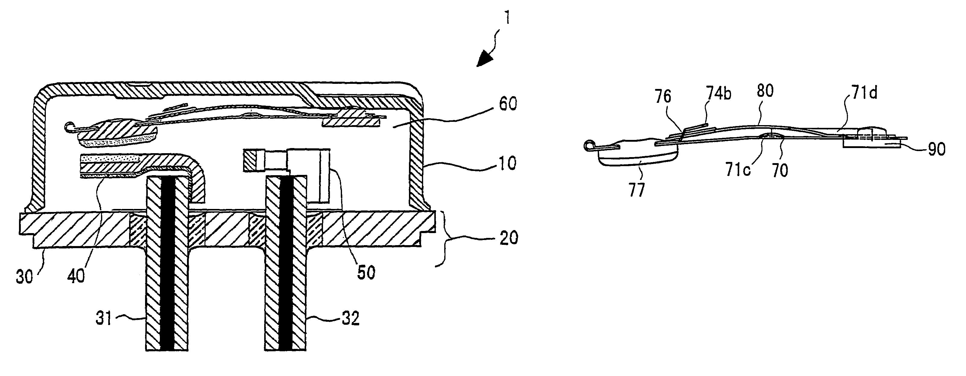
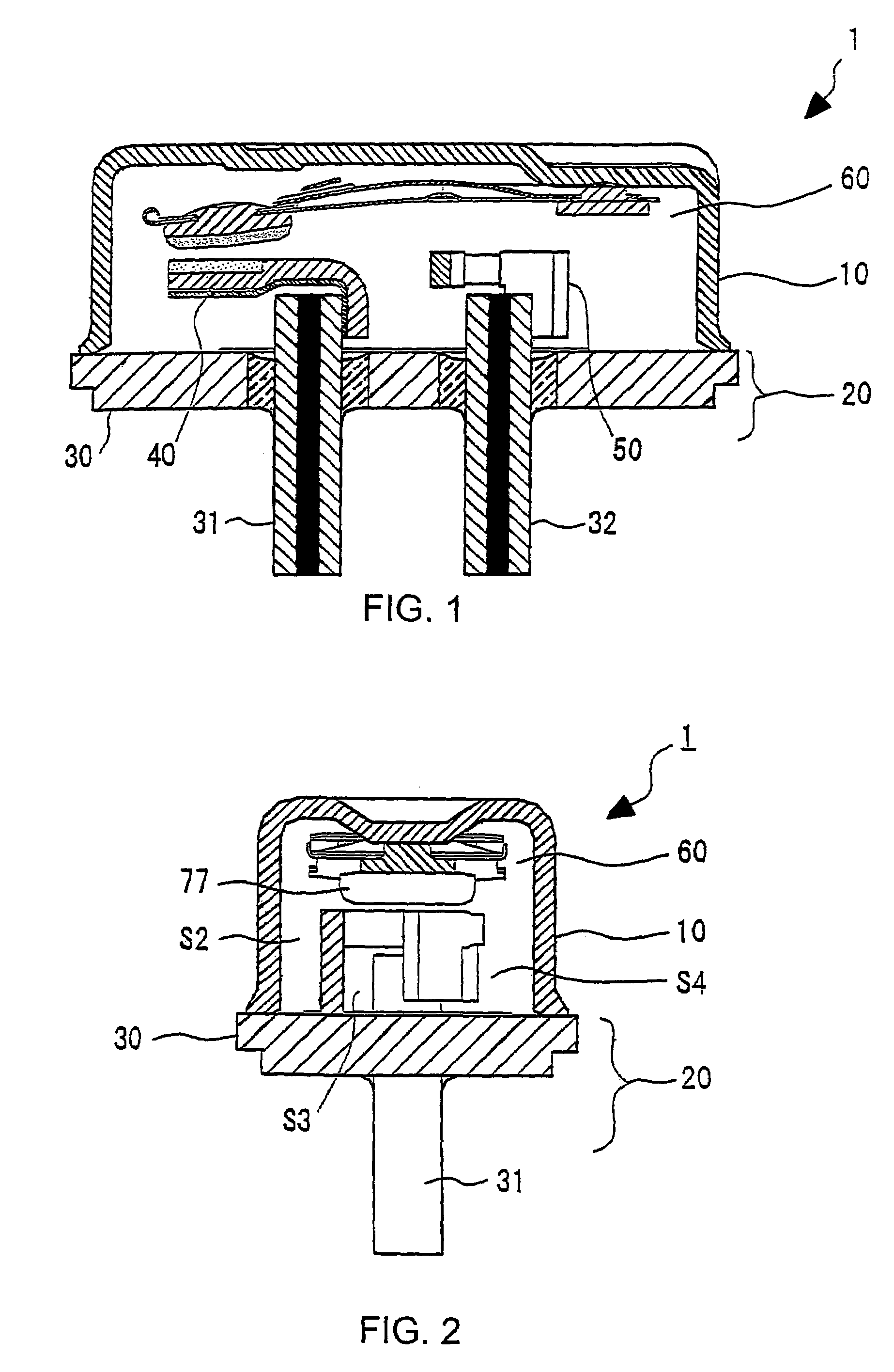
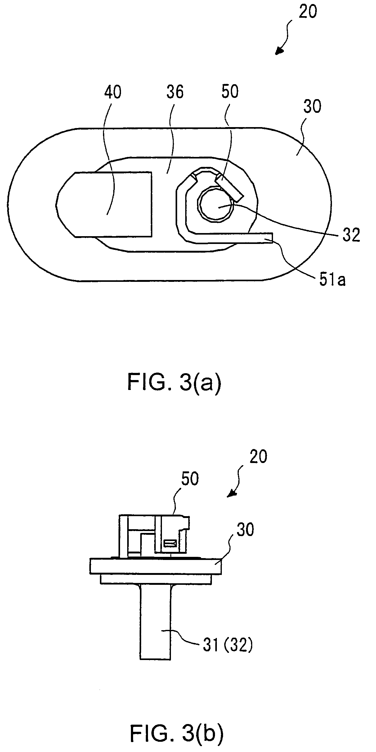
[0039]With particular reference to FIGS. 1 and 2, protector 1 has a cup-shaped metal housing 10 that accommodates a movable plate assembly 60 and forms an internal space or chamber closed by a header pin assembly 20. Header pin assembly 20 includes a header 30, a pair of electrically conductive pins 31 and 32, a stationary contact 40 and a heater 50 (see also FIG. 3). Header 30 is a metal member in the form of a thin plate, such as steel, shown in FIG. 4, with each corner being rounded. Openings 33 and 34 are formed in header 30 for the purpose of accommodating and fixing pins 31 and 32. A stepped portion 30a is formed on the outer periphery of header 31. Pins 31 and 32 are oblong cylindrical metal members that respectively, contain cores 31a and 32a inside. The inner cores 31a and 32a may be of a low-resistance material of copper or copper alloy, with the cores being covered by iron or iron alloy. Pins 31 and 32 have a smaller diameter than openings 33 and 34 of header 30 and are m...


PUM


Abstract

A protector (1) has a metal header (30) that mounts a first terminal (31) and a second terminal (32) electrically isolated from one another. A metallic housing (10) is fixed to the header (30) and forms a chamber. A stationary contact (40) is electrically connected to the first terminal (31), a heater (50) is electrically connected between the second terminal (32) and the header (30), and an arm assembly (60) is arranged inside the chamber, with an end thereof being fixed to the housing. The arm assembly (60) includes an electrically conductive movable plate (70) having a movable contact (77) engageable with the stationary contact (40), a thermally responsive member (80) arranged at a position where it lies over or under the movable plate (70) and an electrically conductive weld slug (90) that fixes the movable plate (70) and the thermally responsive member (80) to the housing (10).

Description

FIELD OF THE INVENTION[0001]This invention relates generally to a motor protector for use with hermetic type electromotive compressors and more particularly to an internal protector which is to be used within hermetic type electromotive compressors.BACKGROUND OF THE INVENTION[0002]An internal protector is typically used in electromotive compressors to detect excess current that flows to the motor or to detect elevated ambient temperatures resulting from an abnormal operation or a constrained operation. Such a protector includes a thermally responsive bimetal element that responds to the excess current or elevated ambient temperature; it opens the circuit that supplies current to the motor on the occurrence of an overload operation or a constrained operation, thereby protecting the motor from damage due to burning or the like.[0003]A fusite pin assembly (or an air-tight sealed terminal assembly) is provided in hermetic type electromotive compressors for the purpose of providing an in...

Claims


Application Information

Patent Timeline
Patent Type & Authority Patents(United States)
IPC IPC(8): H01H37/54H01H37/14F04B39/12F04B39/00F04C23/00F04C28/00F04C29/00H01H37/16H01H71/16H01H81/02
CPCF04C23/008H01H71/164F04C29/0085H01H37/54F04C2240/40F04B39/12H01H37/16
Inventor UNNO, MITSUROTAKASUGI, YOSHIAKISERIZAWA, YUKINOBU
Owner SENSATA TECH MASSACHUSETTS INC
Why Eureka
Try Eureka