Multiplexing in a PDH telecommunications network

a telecommunications network and multi-channel technology, applied in data switching networks, frequency-division multiplexing, time-division multiplexing selection, etc., can solve the problems of link or connection reducing the solution, consuming space for separate atm adaptation elements, and reducing the number of cables and interfaces internal to the network element, saving transmission capacity, and simplifying installation and commissioning work

Inactive Publication Date: 2006-07-11
RPX CORP +1
View PDF12 Cites 22 Cited by
  • Summary
  • Abstract
  • Description
  • Claims
  • Application Information

AI Technical Summary

Benefits of technology

[0016]It is an object of the invention to eliminate the drawbacks described above and to provide a PDH network element capable of flexibly using its PDH capacity, when necessary, also for transfer of a packet data stream, particularly ATM cells, without any inverse multiplexing being needed.
[0021]Since the solution in accordance with the invention enables omission of inverse multiplexing, the auxiliary / peripheral components required by the inverse multiplexer / demultiplexer, such as cabinets or power sources, can simultaneously be omitted. Moreover, the number of cables and interfaces internal to the network element can be reduced. On account of these changes, the overall reliability of the network element is improved and installation and commissioning work is simplified.
[0022]ATM use also saves some transmission capacity, since the cells can be packed directly into the payload portion of the transmission frame (without any need to add other information into the cell stream).

Problems solved by technology

However, the solution described above, utilizing inverse multiplexing / demultiplexing, has certain drawbacks.
First, adding an inverse multiplexer and demultiplexer to the link or connection renders the solution expensive and complex.
Furthermore, a separate ATM adaptation element will be space-consuming, as it requires its own frame in the equipment room.

Method used


Image

  • Multiplexing in a PDH telecommunications network
  • Multiplexing in a PDH telecommunications network
  • Multiplexing in a PDH telecommunications network

Examples


Embodiment Construction

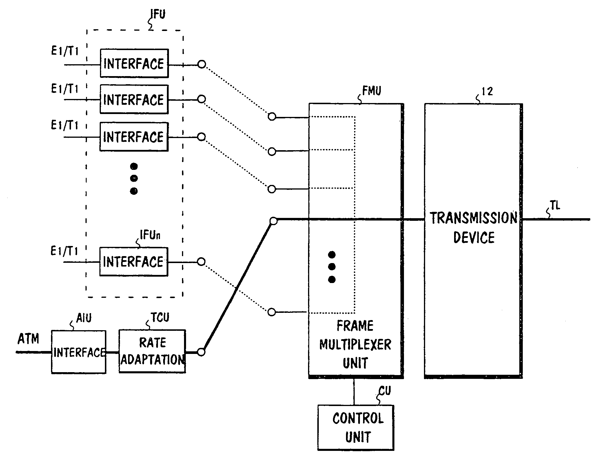
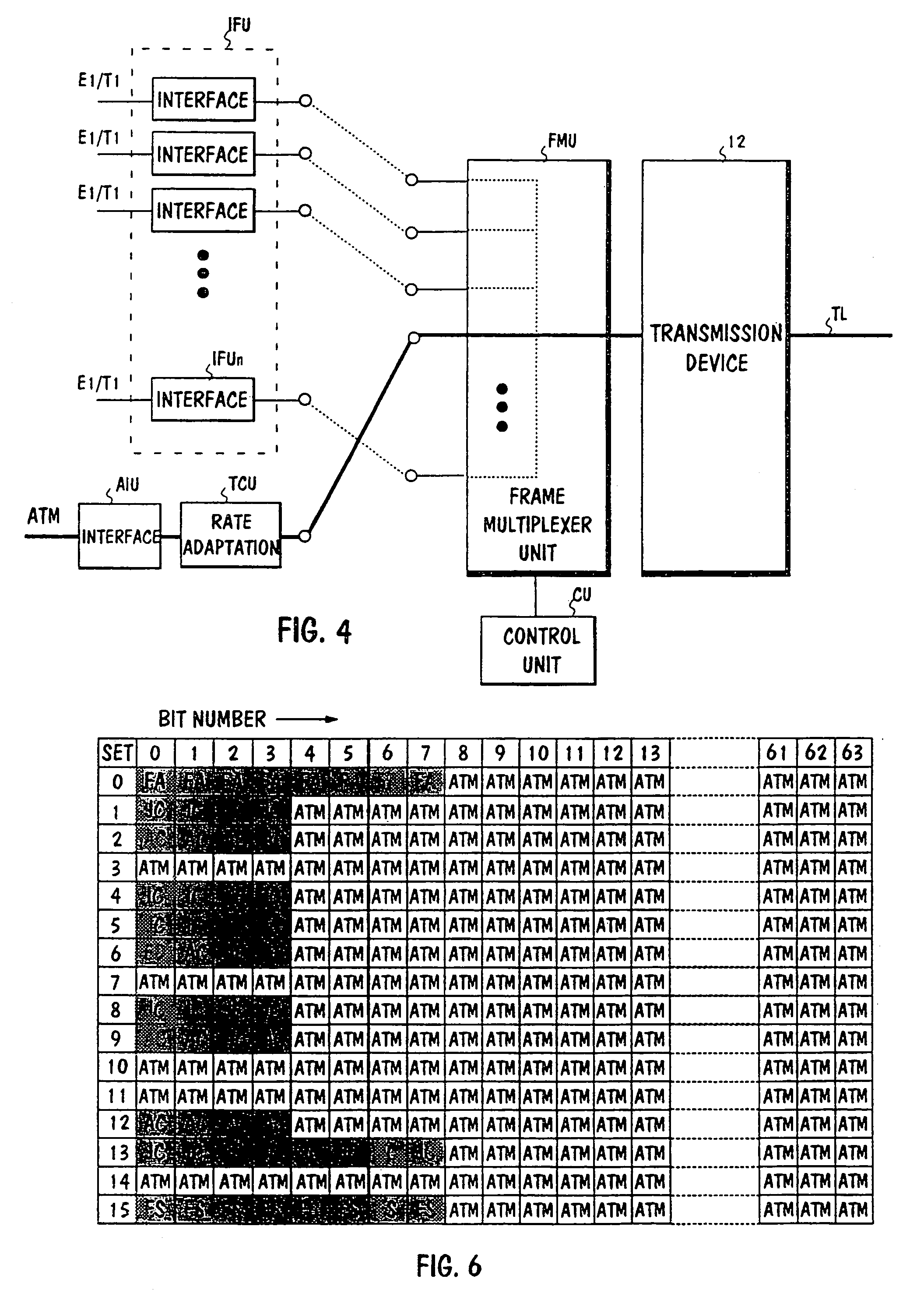
[0030]FIG. 4 is an illustration of the principle of the solution of a network element in accordance with the invention. The frame multiplexing unit FMU of the network element is implemented in such a way that alternatively either PCM signals in accordance with FIG. 1 in a known manner, an ATM cell stream through an interface unit and a rate adaptation unit as described above, or both PCM signals and a cell stream can be connected thereto. When cells are transferred, the cell stream is connected from the output of the rate adaptation unit TCU directly to one input of the frame multiplexing unit. The outbound bit rate to the link is the same in all cases, since the same frame structure is used in all cases.

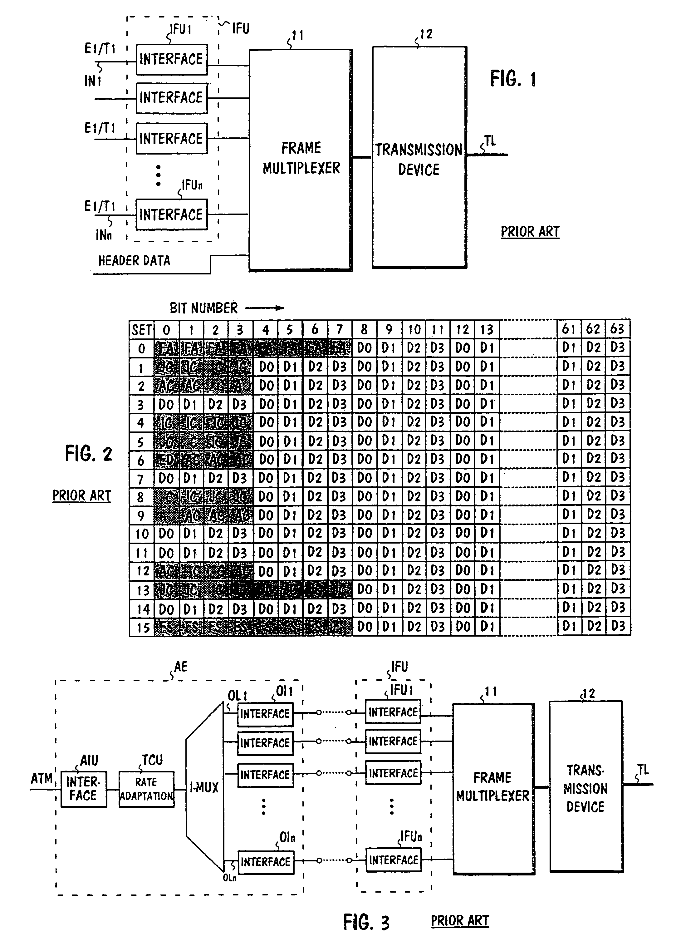
[0031]If only PDH signals are connected to the frame multiplexing unit FMU, they are multiplexed in a known manner into a serial signal to the transmission link TL. This has been denoted with broken line in the figure. If, on the other hand, only an ATM cell stream is connected to t...


PUM


Abstract

The invention relates to a multiplexing method used in a PDH network. Standard PCM signals are received in the network element, at least some of which are multiplexed on a time-division basis into the same outbound transmission frame, the capacity of the payload portion of the frame substantially corresponding to the capacity required by N PCM signals. In order that ATM cells may be transferred more advantageously than heretofore through an existing PDH network, the multiplexing is implemented as configurable in such a way that the total capacity of the payload portion cab be divided between at least two parts of variable capacity in such a way that each part can be allocated a desired portion of the total capacity of the payload portion in accordance with the current transmission requirement. A part of the payload depending on the desired capacity is allocated to at least one traffic source from a group in which a number of PCM signals constitutes a first traffic source and a number of packet data streams constitutes a second traffic source. The invention is specifically intended for transferring ATM traffic through a PDH network.

Description

[0001]This application is a continuation of international application serial number PCT / FI99 / 00451, filed 27 May 1999.FIELD OF THE INVENTION[0002]The present invention relates generally to data transfer implemented in a conventional PDH (Plesiochronous Digital Hierarchy) network. More specifically, the invention relates to how information streams in more modern transmission systems, particularly cell streams in ATM systems, can be transferred across a PDH network.BACKGROUND OF THE INVENTION[0003]PDH is still today the predominating multiplexing hierarchy, even though it was taken into global use already in the 1970s. A multiplexing hierarchy means that an upper hierarchy level system having a higher capacity is constructed by combining a given number of lower hierarchy level systems by means of time division multiplexing. There are three different versions of multiplexing hierarchy, one of which is used in Europe, one in the USA and one in Japan. The European system is also used in ...

Claims


Application Information

Patent Timeline
Patent Type & Authority Patents(United States)
IPC IPC(8): H04J3/02H04J1/02H04J3/22H04J3/16H04L12/56H04Q11/04
CPCH04J3/1623H04J3/1682H04Q11/0478H04L2012/5672H04J2203/0091
Inventor TORMA, ESALAHTI, HARRI
Owner RPX CORP
Why Eureka
Try Eureka