Tri-state transmitter

Inactive Publication Date: 2006-07-11
CISCO TECH INC
View PDF22 Cites 0 Cited by
  • Summary
  • Abstract
  • Description
  • Claims
  • Application Information

AI Technical Summary

Benefits of technology

[0004]In accordance with the present invention, techniques for tri-state communication are provided which substantially eliminate or reduce disadvantages and problems associated with previous techniques. In a particular embodiment, the present invention satisfies a need for increasing bandwidth on existing data lines using a tri-state transmitter, while supporting existing binary logic standards.
[0007]Various embodiments of the present invention provide numerous technical advantages. In a particular embodiment, a tri-state transmitter increases the amount of information communicated over an existing data line without changing clock frequency. Furthermore, the tri-state transmitter implements its functionality using existing binary logic standards to ensure backwards compatibility with devices that only implement a particular binary logic standard. As a result, communication devices can increase data throughput without changing the number of data lines or the clock frequency while still supporting existing binary logic standards. Other technical advantages of the present invention will be readily apparent to one skilled in the art from the following figures, descriptions, and claims.

Problems solved by technology

Given a fixed number of data lines and a predetermined clock frequency, the amount of information communicated by existing binary logic standards is limited.
The allowed bandwidth on existing data lines using binary logic may be insufficient to satisfy increasing capacity demands in a variety of communication systems.
Moreover, current approaches may not allow both an increase in the amount of data for communication on a data line as well as backwards compatibility to existing binary logic standards.

Method used


Image

  • Tri-state transmitter
  • Tri-state transmitter

Examples


Embodiment Construction

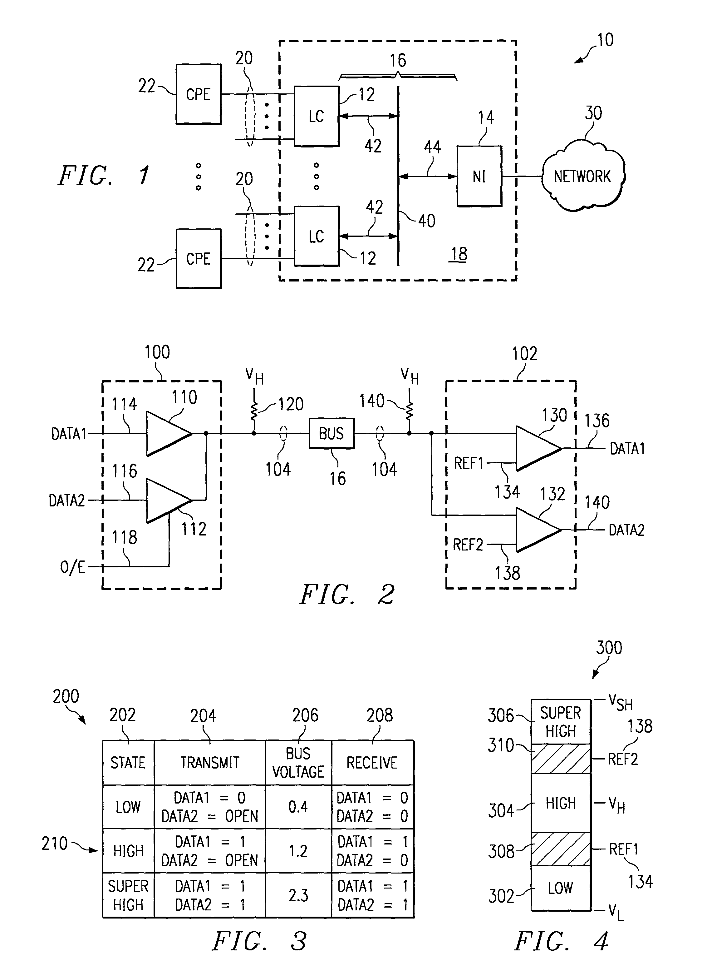
[0013]FIG. 1 illustrates a communication system 10 that includes a number of linecards 12 coupled to a network interface card 14 using bus 16. In a particular embodiment, linecards 12 and / or network interface 14 include tri-state transmitters that communicate information using bus 16. Linecards 12, network interface 14, and bus 16 may be components of a communication server 18, such as a digital subscriber line access mutliplexer (DSLAM) that provides broadband data services to customers.

[0014]Each linecard 12 includes a number of subscriber lines 20 that, directly or through intermediate components, couple linecard 12 to customer premises equipment (CPE) 22. CPE 22 allows customers to receive a variety of communication services that allow for the exchange of voice, video, data, and other information (generally referred to as media) between CPE 22 and communication server 18. Communication server 18 may include any number of linecards 12 to service customers in communication system ...


PUM


Abstract

A tri-state transmitter drives a data line to a first state if a first data signal is a logic zero and releases the data line to a second state if the first data signal is a logic one. The tri-state transmitter also drives the released data line to a third state if the first data signal is a logic one and the second data signal is a logic one.

Description

TECHNICAL FIELD OF THE INVENTION[0001]The present invention relates generally to communications, and more particularly to a tri-state transmitter.BACKGROUND OF THE INVENTION[0002]Traditional binary logic circuits communicate information using two states that include a low voltage state or logic zero and a high voltage state or logic one. Using predetermined voltage levels for logic zero and logic one, these circuits communicate information at a given clock speed, where each cycle of the clock may represent a logic one or a logic zero. Several binary logic standards such as Gunning Transceiver Logic (GTL) and Stub Series Terminated Logic (SSTL) define the different voltage levels and timing requirements to allow receivers to resolve the logic zero and logic one signals.[0003]Given a fixed number of data lines and a predetermined clock frequency, the amount of information communicated by existing binary logic standards is limited. The allowed bandwidth on existing data lines using bin...

Claims


Application Information

Patent Timeline
IPC IPC(8): H04B1/38
CPCH04L25/4923H04L25/062
Inventor WANG, LI T
Owner CISCO TECH INC
Why Eureka
Try Eureka