Power saving management system and power saving managing method for forwarding an updated power mode shift time to a plurality of output apparatuses over a network

a management system and power mode technology, applied in the direction of digital output to print units, process and machine control, instruments, etc., can solve the problems of vain consumption of electric power supplied meanwhile to each apparatus in the output apparatus, use environment of the output apparatus, and high frequency all the time request for images is rare, so as to reduce the electric power consumption of the output apparatus and reduce the electric power consumption

Active Publication Date: 2006-07-11
CANON KK
View PDF8 Cites 20 Cited by
  • Summary
  • Abstract
  • Description
  • Claims
  • Application Information

AI Technical Summary

Benefits of technology

[0012]Therefore, as an output apparatus such as copying apparatus, printer, or the like, there has already been proposed a printing apparatus which intends to largely reduce the electric power consumption by constructing in a manner such that a control apparatus provided in the apparatus has time measuring means such as a first timer device or the like, the timer device is activated by the operation of the user, and when time measured by the timer device is equal to time which has also been preset by the user, the control unit of the printer shuts off the power supply to each apparatus except for the necessary minimum power supply.
[0013]By using the above construction, the output apparatus is shifted to a sleep mode in the time zone when the number of image outputting requests decreases largely and in the time zone when the image outputting request is hardly made, so that the reduction of the electric power consumption of the output apparatus can be expected.

Problems solved by technology

However, a use environment of the output apparatus such that the image outputting request is made at a high frequency all the time is rare.
In the case where the image outputting request to the output apparatus is not made for a long time, the electric power supplied meanwhile to each apparatus in the output apparatus is vainly consumed.

Method used


Image

  • Power saving management system and power saving managing method for forwarding an updated power mode shift time to a plurality of output apparatuses over a network
  • Power saving management system and power saving managing method for forwarding an updated power mode shift time to a plurality of output apparatuses over a network
  • Power saving management system and power saving managing method for forwarding an updated power mode shift time to a plurality of output apparatuses over a network

Examples


embodiment 1

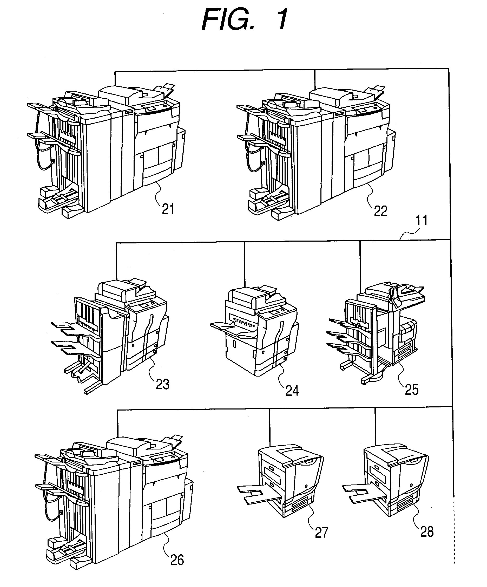
[0040]FIG. 1 is a diagram showing a schematic construction of a network system to which the invention is embodied.

[0041]Reference numeral 11 denotes a network which mutually connects output apparatuses 21 to 28 and functions as a transfer medium of information. Although not shown, a computer, a workstation, a terminal apparatus, and the like are also connected to the network 11. Network services such as sharing of the information, distributed processes, and the like are provided to the users.

[0042]Reference numerals 21 to 28 denote the output apparatuses connected to the network. Generally, the output apparatuses function as printers. The output apparatuses 21 to 28 receive image outputting requests from the computer and workstation (not shown) serving as clients and generate image data transferred via the network.

[0043]Each of the output apparatuses 21 to 26 has a construction such that the output apparatus itself also has an image reading apparatus, and a function as a copying app...

embodiment 2

[0100]FIG. 11 is a diagram showing a schematic construction of the network system in the embodiment. Reference numeral 11 denotes the network. A server 12, the output apparatuses 21 to 28, and computers and workstations 31 to 34 are connected to the network 11, respectively. The network 11 plays a role as a transfer medium of information.

[0101]A function of a timer management server as a feature of the invention has been built in as one system of the server 12 and provides a server service in the network together with other functions, the server 12 has a construction as shown in FIG. 21 (each of the following embodiments also has a similar construction). In FIG. 21, reference numeral 101 denotes a CPU for controlling the operation of the whole server; 102 a ROM in which a control procedure of the CPU 101 has been stored; 103 a RAM which provides a work area (including each data area, which will be explained hereinlater) of the CPU 101; 104 a timer (one or a plurality of timers) serv...

embodiment 3

[0127]Since a construction of hardware of the embodiment 3 is similar to that of the embodiment 2, its detailed description is omitted.

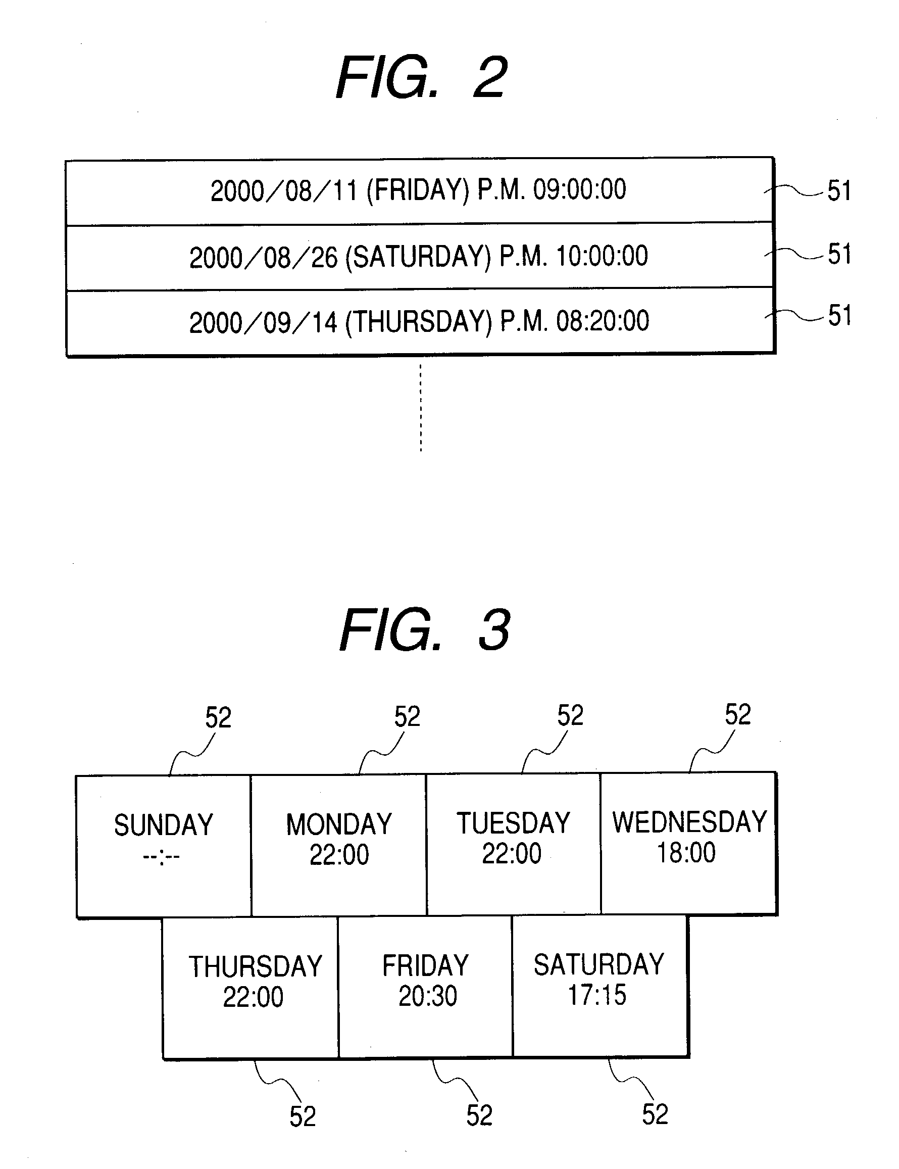
[0128]FIGS. 16 and 17 are diagrams showing an outline of a mechanism such that the power saving mode shift time information data stored in the server 12 is reflected to the power saving mode shift time information areas of the records 51 and 52 in each of the output apparatuses 21 to 28, respectively.

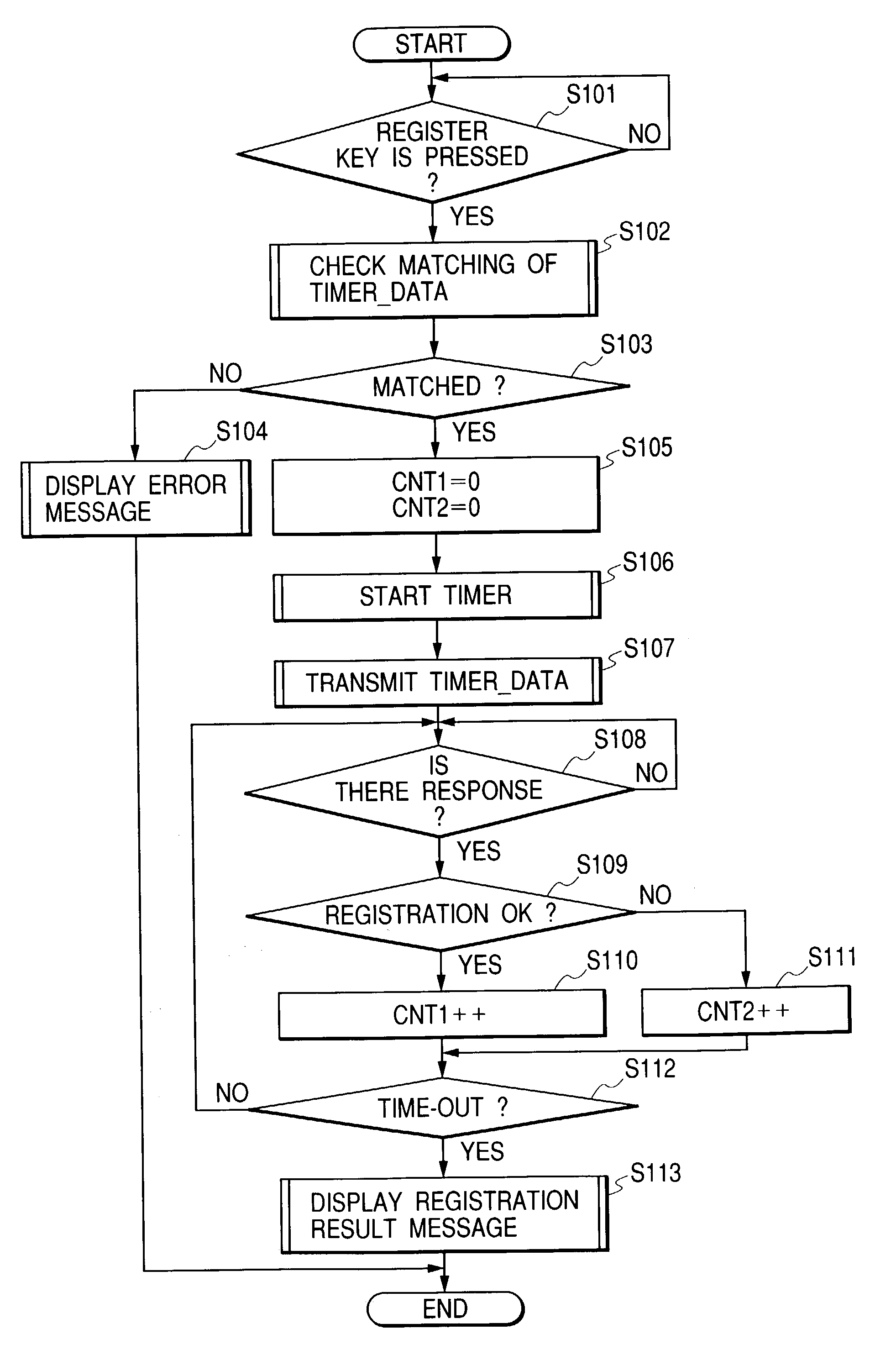
[0129]FIG. 16 is a diagram showing a state where the output apparatus 21 transmits an obtaining request of the power saving mode shift time information to the server 12 connected to the same network 11. FIG. 17 is a diagram showing a state where the power saving mode shift time information data from the server 12 is received and the power saving mode shift time information data built in the output apparatus 21 is updated.

[0130]First, in FIG. 16, the output apparatus 21 transmits the obtaining request of the power saving mode shift time information to the...


PUM


Abstract

A managing apparatus has a RAM for storing power saving mode shift time and notifies output apparatuses of the stored power saving mode shift time via a network. Each output apparatus is shifted to a power saving mode when measured time by a built-in timer reaches the notified power saving mode shift time.

Description

BACKGROUND OF THE INVENTION[0001]1. Field of the Invention[0002]The invention relates to a power saving management system and, more particularly, to a power saving management system which can reduce the whole electric power consumption of the output apparatuses in a printer processing system in an environment such that the output apparatuses such as a plurality of copying apparatuses, printers, facsimiles, and the like and a workstation, a personal computer, an information terminal, and the like which are used by the user are connected to a network.[0003]2. Related Background Art[0004]In recent years, a computer network (hereinafter, simply referred to as a network) in which various computers and their peripheral equipment are connected so that information can be bidirectionally communicated has been established. Such a computer network is a technique which is drawing much attention because productivity and efficiency can be remarkably improved by a method whereby a plurality of use...

Claims


Application Information

Patent Timeline
Patent Type & Authority Patents(United States)
IPC IPC(8): G06F1/26B41J29/38G03G21/00G06F1/32G06F3/12
CPCG06F1/3203G06F1/3284Y02B60/1267Y02D10/00
Inventor YOSHIKAWA, TOMOYASU
Owner CANON KK
Why Eureka
Try Eureka