Ventilator with dual gas supply

a ventilator and gas supply technology, applied in the direction of valve details, valve arrangement, operating means/releasing devices, etc., can solve the problems of higher motor wear, inability to adjust the speed and output quickly enough to correct pressure changes, and the ventilator b>100/b> of the prior art has drawbacks, so as to achieve the effect of reducing the difference in gas supply

Inactive Publication Date: 2006-07-18
TYCO HEALTHCARE GRP LP
View PDF24 Cites 187 Cited by
  • Summary
  • Abstract
  • Description
  • Claims
  • Application Information

AI Technical Summary

Benefits of technology

[0015]A method of pressure regulation for a ventilator is provided according to an embodiment of the invention. The method comprises the steps of providing a positive relative pressure gas supply, providing a negative relative pressure gas supply, and detecting a gas supply difference between a gas supply provided to a gas delivery device of the ventilator and a predetermined gas supply. The method further comprises the steps of generating a feedback signal that is substantially related to the gas supply difference, and actuating a diverter valve to communicate the positive relative pressure gas supply and the negative relative pressure gas supply to the gas delivery device in order to substantially minimize the gas supply difference.

Problems solved by technology

However, a variable blower speed ventilator 100 of the prior art has drawbacks.
However, if the ventilator circuit resistance becomes too great, a blower may not be able to adjust its speed and output quickly enough to correct for pressure changes.
These quick changes in motor speed and direction may cause unacceptable levels of motor heating, may require more electrical power to achieve a desired pressure, may cause much higher levels of motor wear, and still do not provide a satisfactorily fast pressure response.

Method used


Image

  • Ventilator with dual gas supply
  • Ventilator with dual gas supply
  • Ventilator with dual gas supply

Examples


second embodiment

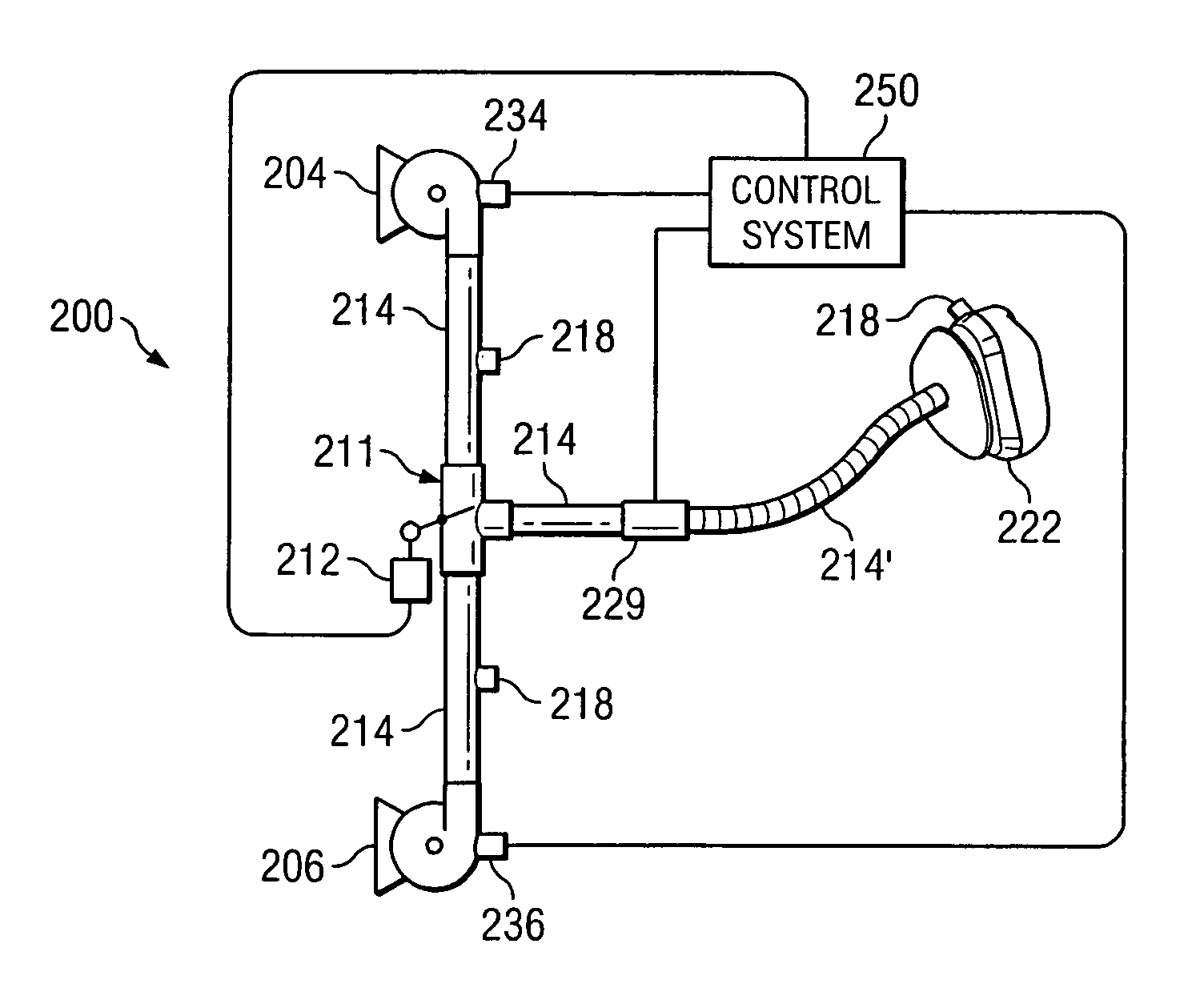
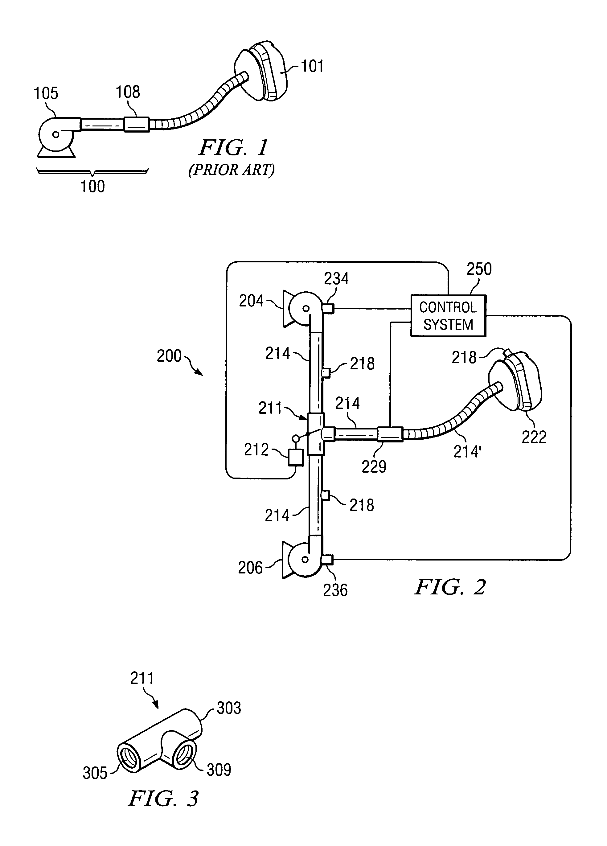
[0039]In a second embodiment, the feedback sensor 229 is a flow volume sensor positioned on or between the diverter valve 211 and the gas delivery device 222. The flow volume sensor 229 measures a flow volume of gas. The flow volume may be used to signify pressure changes and determine when the patient is inhaling or exhaling (see FIG. 5 and accompanying discussion below). The flow volume sensor 229 may generate a feedback signal that is substantially related to the gas supply flow volume. The feedback signal may be compared to a predetermined or desired flow volume or flow volume profile in order to generate a flow volume difference. The flow volume difference may be used to actuate the diverter valve 211 according to any known feedback and control algorithm.

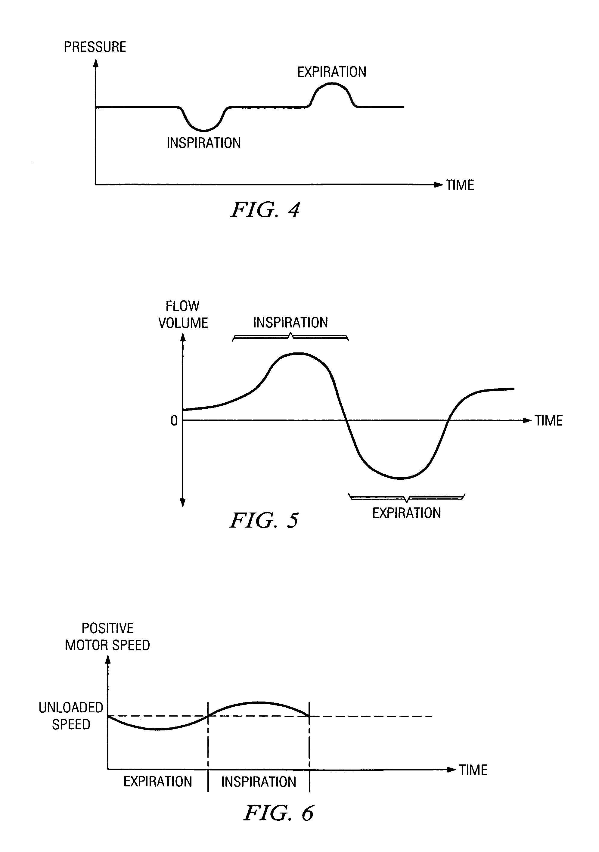
[0040]FIG. 5 is a flow volume graph of a representative flow volume during a typical breathing cycle. This may be the flow volume at the gas delivery device 222. As can be seen from the graph, the gas flow volume varies regular...

third embodiment

[0041]In a third embodiment, one or more motor speed sensors 234 and 236 are used to control the diverter valve 211. In the two motor speed sensors embodiment, for example, the point in time when the motor speed of the positive relative pressure gas supply 204 drops, patient inhalation has stopped and exhalation has begun. As the positive pressure continues to be supplied, the pressure in the ventilator increases when the patient stops inhaling (i.e., an airflow backup occurs). This increase in pressure will cause the motor of the positive relative pressure gas supply 204 to slow down. Therefore, the control system 250 may now control the actuator 212 and move the diverter valve 211 to select the negative pressure port 305 and the negative relative pressure gas supply 206, or select a greater opening percentage for the negative pressure port 305.

[0042]Conversely, when the motor speed of the negative relative pressure gas supply 206 drops, as detected by the motor speed sensor 236, e...


PUM


Abstract

A method of pressure regulation and a ventilator are provided. The ventilator includes a positive relative pressure gas supply, a negative relative pressure gas supply, and a diverter valve. The diverter valve includes a positive pressure port connected to the positive relative pressure gas supply, a negative pressure port connected to the negative relative pressure gas supply, and a gas supply port communicating with a gas delivery device. The ventilator preferably further includes a feedback sensor that detects a gas supply difference between a gas supply and a predetermined gas supply and generates a feedback signal that is substantially related to the gas supply difference. The ventilator preferably further includes a diverter valve actuator communicating with the diverter valve and operating the diverter valve to communicate the positive relative pressure gas supply and the negative relative pressure gas supply to the gas supply port of the diverter valve based upon the feedback signal.

Description

CROSS REFERENCE OF RELATED APPLICATION[0001]This application is a continuation of application Ser. No. 09 / 691,139, filed Oct. 19, 2000.BACKGROUND OF THE INVENTION[0002]1. Field of the Invention[0003]The present invention relates generally to the field of medical ventilators.[0004]2. Description of the Background Art[0005]A medical ventilator is a device used to deliver a gas or gases to a patient. This may include air or oxygen, and may also include a variety of additive medicines or treatments. The gas is supplied to a patient via a gas delivery device such as a mask, a nasal cannula, or a tracheostomy tube. The ventilator may be used in cases where it merely assists a patient's breathing (respiratory insufficiency), or may be used in cases where the ventilator must perform breathing for the patient (respiratory failure or when the patient is under the influence of anesthesia). The ventilator may provide a constant pressure airflow, may provide a cyclic airflow, or may provide othe...

Claims


Application Information

Patent Timeline
Patent Type & Authority Patents(United States)
IPC IPC(8): A61M16/00
CPCA61M16/00A61M16/0009A61M16/0066A61M2016/0039A61M16/06A61M16/026
Inventor HANSEN, GARY
Owner TYCO HEALTHCARE GRP LP
Why Eureka
Try Eureka