Blood component separator disk

a technology of separator disk and component, which is applied in the direction of separation process, centrifuge, laboratory glassware, etc., can solve the problems of reducing the separation efficiency of the system, affecting the placement of the interface,

Inactive Publication Date: 2006-07-18
HARVEST TECH
View PDF28 Cites 127 Cited by
  • Summary
  • Abstract
  • Description
  • Claims
  • Application Information

AI Technical Summary

Benefits of technology

[0006]Decant of the supernatant can be either by gravity drain or by centrifugal transfer, and a main function of the disk is to restrict the flow of the component below it, e.g., red blood cells, during decant. This ensures that the supernatant is not contaminated and increases the efficiency of the process.
[0009]In either of these embodiments, the specific gravity of the disk and its shape may be chosen so that a major part of the upper surface lies just below the interface, thus facilitating release of the supernatant from the disk during decanting. This upper surface is also preferably curved to match the cylindrical shape the interface assumes during centrifugation.

Problems solved by technology

One problem with the arrangement shown in the '331 Wells patent, however, is that the position of the interface varies with the particular proportions of the components (e.g., the hematocrit) of the blood to be processed.
Such a position of the shelf will hinder the flow of the components near the interface during decanting, thus retaining significant amounts of these components in the first chamber and reducing the separation efficiency of the system.

Method used


Image

  • Blood component separator disk
  • Blood component separator disk
  • Blood component separator disk

Examples


Embodiment Construction

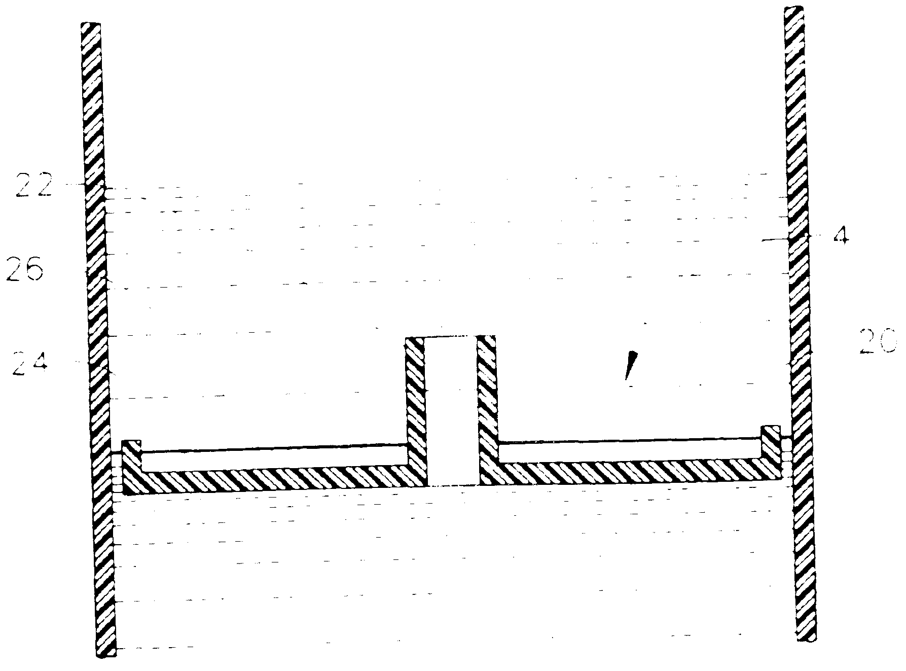
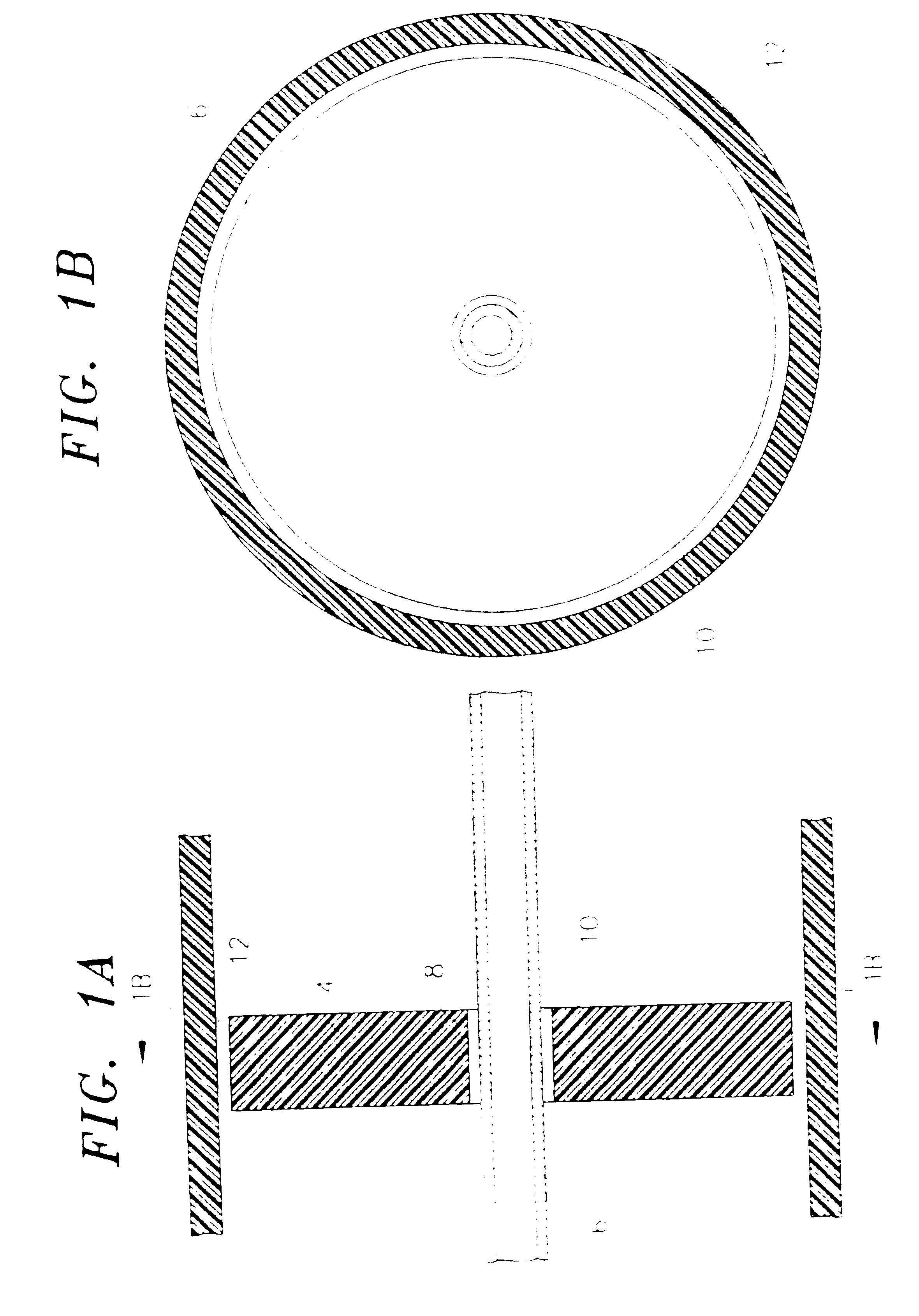
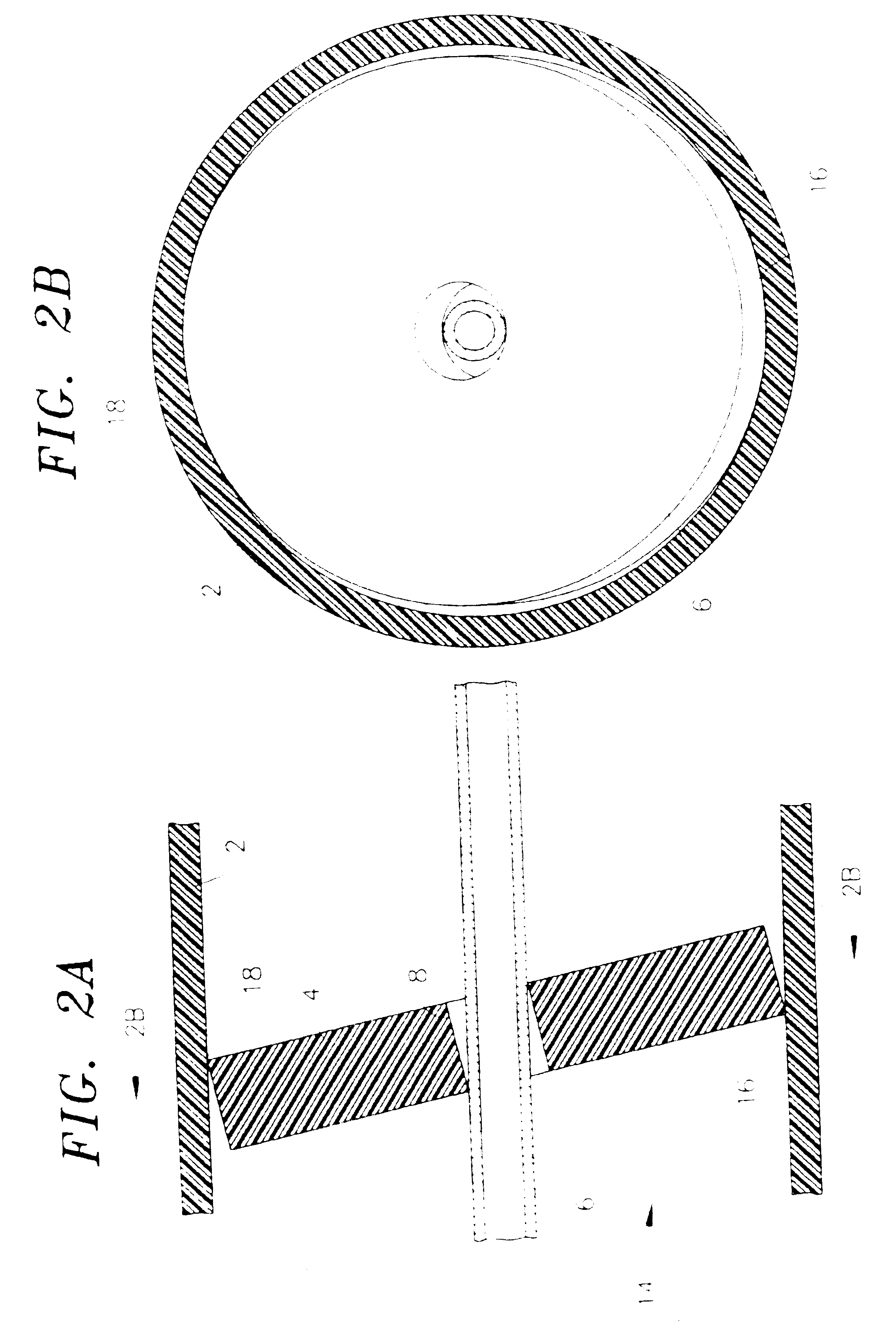
[0017]With reference to FIGS. 1 and 2, one chamber 2 of a processing tube, such as that shown in the '331 Wells patent has a separator disk 4 in accordance with the invention supported therein by a central shaft 6. The shaft 6 is designed to direct fluid introduced into the chamber to the bottom of the chamber. This precludes the formation of an air bubble at the bottom of the chamber, particularly when the bottom of the chamber is tapered. Thus, fluid is introduced into the chamber by inserting a cannula attached to a syringe containing blood into the shaft 6 and discharging the blood from the syringe into the chamber. A central opening 8 in the disk receives the shaft 6 in such a manner that the disk easily slides along the shaft.

[0018]The shaft 6 may not be necessary in all instances, for example, when the bottom of the processing tube is flat. In that instance the disk does not have a central hole.

[0019]The disk is preferably made of material having a specific gravity that allow...


PUM

PropertyMeasurementUnit
specific gravityaaaaaaaaaa
lengthaaaaaaaaaa
lengthaaaaaaaaaa

Abstract

A separator disk (4) for use in centrifugal separation of components is designed to automatically position itself during separation at the interface between the supernatant and the remaining components. Preferably the interface is between plasma and red blood cells.

Description

[0001]This application claims the benefit of Provisional application Ser. No. 60 / 200,150, filed Apr. 28, 2000.TECHNICAL FIELD[0002]This invention relates to methods and apparatus for use in the separation of fluids into components having different specific gravities. The invention finds particular utility in the centrifugal separation of the components of blood.BACKGROUND[0003]Centrifugal separation of blood into components of different specific gravities, such as red blood cells, white blood cells, platelets, and plasma is known from U.S. Pat. No. 5,707,331 (Wells). The apparatus shown in that patent employs a disposable processing tube having two chambers, and blood to be separated into components is placed in one of the chambers. The processing tube is placed in a centrifuge, which subjects the blood to centrifugal forces to separate the components. The supernatant is then automatically decanted into the second of the chambers.[0004]To retain, principally, the red blood cells dur...

Claims


Application Information

Patent Timeline
Patent Type & Authority Patents(United States)
IPC IPC(8): B04B7/12G01N33/48A61M1/02A61M1/36B01D17/02B01D21/24B01L3/14B04B5/02
CPCA61M1/3693B01D17/0217B01D21/2433B04B11/00B01D21/262B04B7/00B01L3/50215B01D21/26A61M1/029B01D2221/10G01N33/491B04B7/12B01L3/5021B01L2300/0803B01L2300/0832
Inventor ELLSWORTH, JAMES R.LEVESQUE, STEVEN F.
Owner HARVEST TECH
Why Eureka
Try Eureka