Shuttered lamp assembly and method of cooling the lamp assembly

a technology of lamp assembly and shutter mechanism, which is applied in the direction of optical radiation measurement, furnaces, instruments, etc., can solve the problems of wasting energy, affecting the efficiency of the lamp, and the time period necessary to power up and power down may be too long for a high-productivity environment, so as to achieve the effect of effective shutter mechanism, efficient cooling system and method integrated into the shutter mechanism, and increasing bulb efficiency

Active Publication Date: 2006-07-18
NORDSON CORP
View PDF17 Cites 31 Cited by
  • Summary
  • Abstract
  • Description
  • Claims
  • Application Information

AI Technical Summary

Benefits of technology

[0008]The present invention generally relates to a UV lamp assembly which provides both an effective shuttering mechanism using reflector panels of the assembly itself, and an efficient cooling system and method integrated into the shuttering mechanism. The cooling system ensures that adequate cooling of the UV lamp bulb occurs in both the shuttered and unshuttered positions. In the unshuttered or open position in which a substrate is being irradiated with UV light, the lamp bulb is be contacted with a high flow of cooling air since the assembly is typically at full power. During the shuttered or closed position, the power to the lamp bulb is automatically reduced and less cooling air flow contacts the lamp bulb. The present invention provides an efficient manner of achieving proper bulb cooling in both the open and closed positions, while achieving increased bulb efficiency.

Problems solved by technology

Turning the power to the lamp on and off is one possible way to achieve the desired on / off effect, but is not practical in many situations.
For example, the time period necessary to power up and power down may be too long for a high productivity environment.
Also, constantly powering a lamp on and off can waste energy and shorten bulb life.
One challenge faced with mechanical shutter systems is cooling the lamp bulb when the shutters are in the closed position.
When shutters are used, and they are closed, this generally restricts the air flow and allows excessive heat to build up around the lamp bulb which can harm the bulb and shorten its life.
Without support, these thin panels can easily overheat and warp from the heat of the bulb.
This works well for the outer reflector panels, but not as well for the center section.
This would lead to higher costs of manufacture.
Moreover, thicker aluminum in which holes can be punched or otherwise formed prior to bending to the necessary reflective surface is not available in a highly polished, mirror finish.
Finally, due to the complexity of existing shutter mechanisms, the reflector panels in existing designs are difficult to replace as they require disassembly of the lamp head.

Method used


Image

  • Shuttered lamp assembly and method of cooling the lamp assembly
  • Shuttered lamp assembly and method of cooling the lamp assembly
  • Shuttered lamp assembly and method of cooling the lamp assembly

Examples


Embodiment Construction

[0019]This is a description of the preferred embodiment of the present invention, but the details discussed herein are not to be construed as limitations on the scope of the invention except to the extent of the claims appended hereto. In addition, although spatial references, such as the terms “upper” and “lower” and other similar terms are used herein, these terms are not meant to be limiting in nature but are used for the sake of more easily discussing the drawings. It will be understood that an assembly constructed according to the invention may be placed in any number of spatial orientations.

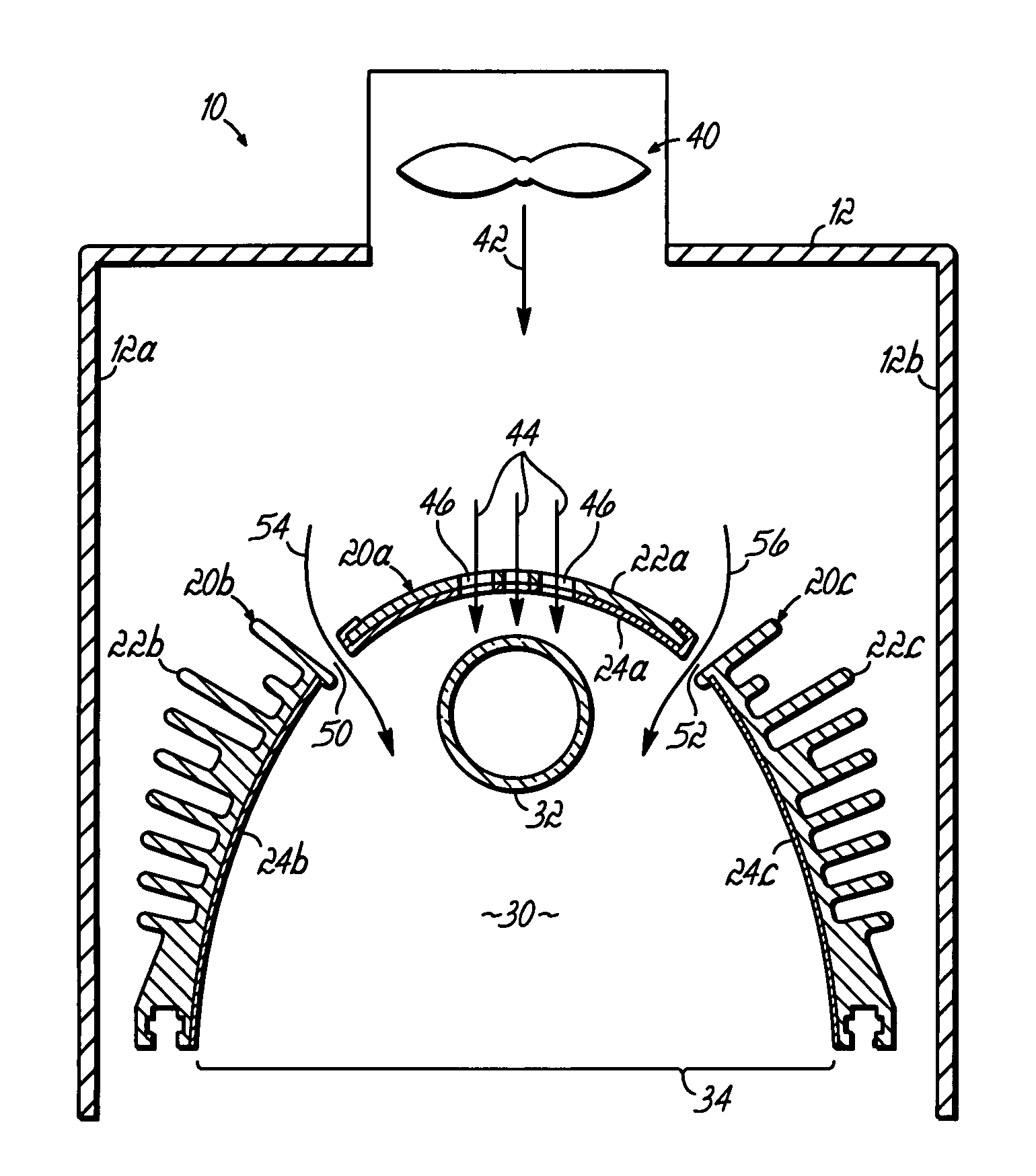
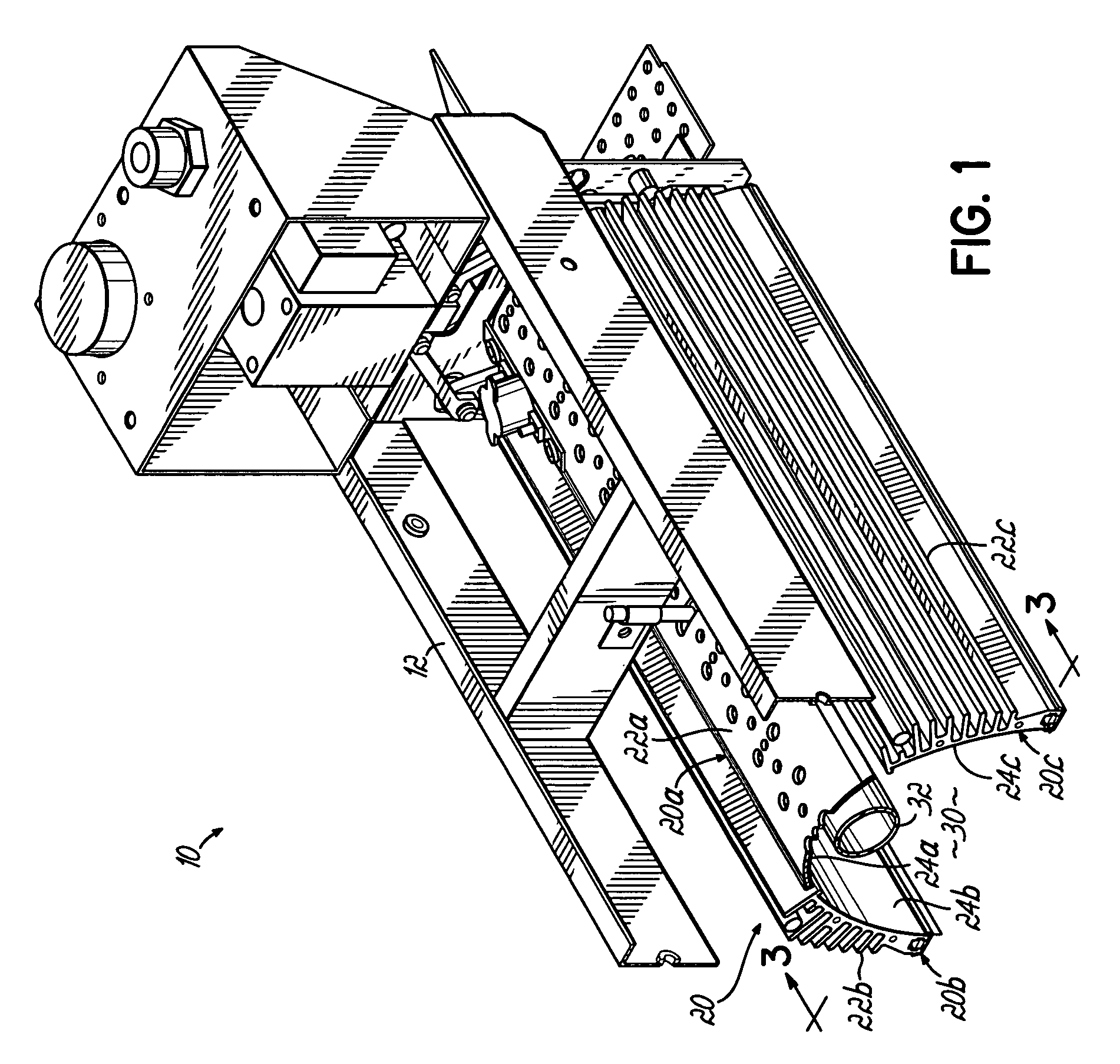
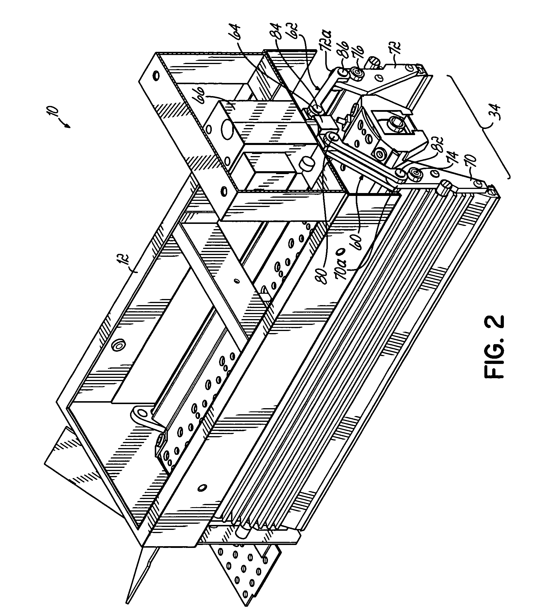
[0020]FIGS. 1 and 2 respectively illustrate perspective views of a partially disassembled electrode lamp assembly 10 for emitting UV radiation. For clarity, these drawing figures do not illustrate a housing and various other conventional structure normally associated with such lamp assemblies. However, a suitable lamp assembly useful for incorporating the present invention is an industrial ...


PUM


Abstract

An ultraviolet lamp assembly includes an elongate lamp bulb, a central reflector mounted above the bulb and side reflector panels mounted on opposite sides of the central reflector panel. A first air gap is located between the first side reflector panel and the central reflector panel when the first and second side reflector panels are in the open position. A second air gap is located between the second side reflector panel and the central reflector panel when the first and second side reflector panels are in the open position. An air moving device is configured to direct cooling air downwardly through the perforations at the upper portion of the bulb and downwardly through the first and second air gaps at the lower portion of the bulb.

Description

FIELD OF THE INVENTION[0001]The present invention generally relates to lamp assemblies, especially those emitting ultraviolet radiation for various industrial purposes.BACKGROUND OF THE INVENTION[0002]Many applications in industry require the use of an ultraviolet (UV) light emitting lamp assembly. For example, ultraviolet light is often used to cure various UV curable materials, such as adhesives used to assemble products or packaging, and inks used on such products and packaging. UV lamp assemblies may be microwave powered or electrode powered and typically include a reflector which partially surrounds an elongate lamp bulb for reflecting the ultraviolet radiation emitted by the bulb onto the substrate, such as products or product packaging. The reflector commonly has a reflective surface which is elliptical or parabolic in shape and the lamp bulb is mounted along the symmetrical centerline and adjacent the apex of the reflector. The reflector increases the intensity of radiation ...

Claims


Application Information

Patent Timeline
Patent Type & Authority Patents(United States)
IPC IPC(8): F21V29/00
CPCF26B3/28G01J3/10G01J3/0286
Inventor SCHMITKONS, JAMES W.SHANABERGER, JAN L.
Owner NORDSON CORP
Why Eureka
Try Eureka