Viscoelastic foam layer and composition

a technology of viscoelastic foam and composition, applied in the field of viscoelastic foam layer and composition, can solve the problems of not recovering or reversing to any significant degree, unable to effectively absorb the energy of higher velocity impacts compared to rigid foams like eps, and rigid urethane foams also correspondingly begin to suffer

Inactive Publication Date: 2006-07-18
TEAM WENDY
View PDF86 Cites 21 Cited by
  • Summary
  • Abstract
  • Description
  • Claims
  • Application Information

AI Technical Summary

Problems solved by technology

However, traditional rigid and semi-rigid foams exhibit satisfactory energy absorption only above certain impact speeds, e.g. above about 4–7 meters / second (m / s) for expanded polystyrene (EPS) which is the most common rigid foam found in bicycle and motorcycle helmets.
An additional problem with EPS foams is that they are non-recovering; i.e. they do not recover or rebound to any significant degree once they have been crushed from an impact.
Existing semi-rigid polyurethane foams address these shortcomings to some extent as a result of their limited viscoelastic properties.
Though existing semi-rigid foams can be compressed or deflected at lower impact velocities to absorb some degree of the impact energy, they cannot effectively absorb the energy from higher velocity impacts compared to rigid foams like EPS.
However, these more rigid urethane foams also correspondingly begin to suffer from the same drawbacks, which initially led the designers away from rigid foams like EPS.
The more rigid the foam, the less it will recover after being crushed, and the poorer low to moderate impact energy absorption it will provide.

Method used


Image

  • Viscoelastic foam layer and composition
  • Viscoelastic foam layer and composition
  • Viscoelastic foam layer and composition

Examples


example 1

[0049]Eight foams were prepared from compositions according to the invention. Each of the eight foams was prepared by combining Part A and Part B compositions having the components in the amounts listed in Table 2 below for the respective foam.

[0050]

TABLE 2Part A and B compositions for eight foams prepared accordingto the inventionFoamElement12345678Part B [components listed in part by weight (pbw)]Monoethanolamine- / 49.59.51115149.5based polyolTriethanolamine-252110.510.5 / / 1110.5based polyolEthylenediamine-26263131403626 / Based polyolFilled polyol2424244924242416Unfilled polyol252525 / 25252564Black Paste66666666Water3333332.54Catalyst 111.251.51.51.150.850.90.35Catalyst 2 / / 0.05 / 0.10.1750.150.25Catalyst 310.25 / / / / / / Catalyst 40.50.5 / / / / / / Part AIsocyanate (wt. %)2323232323232323Foam Index11510799100999610095

[0051]In Table 2, the following listed elements represent the following components:[0052]The monoethanolamine-based polyol is a polyether polyol having an OH No. of about 700;[0053]Th...

example 2

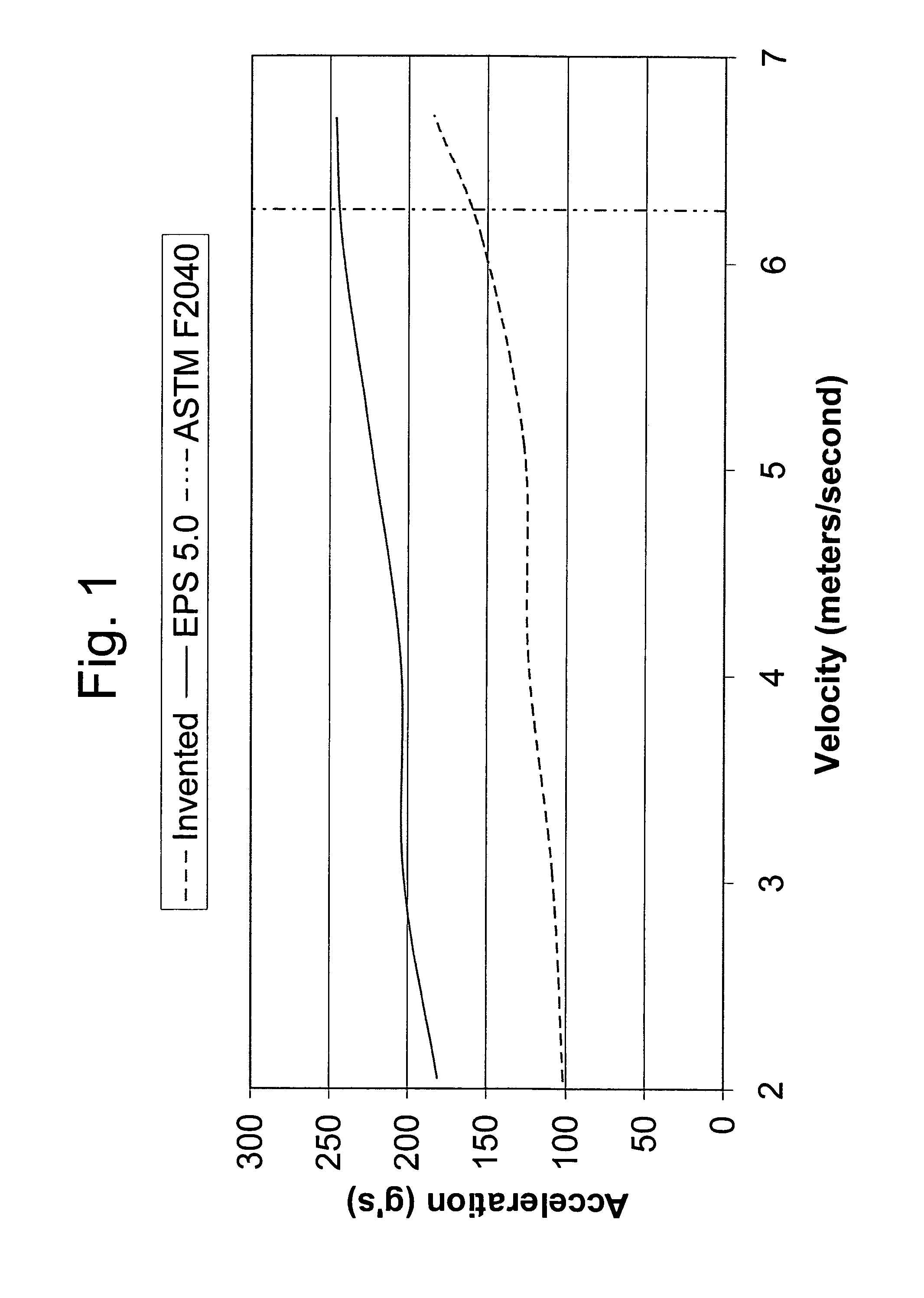
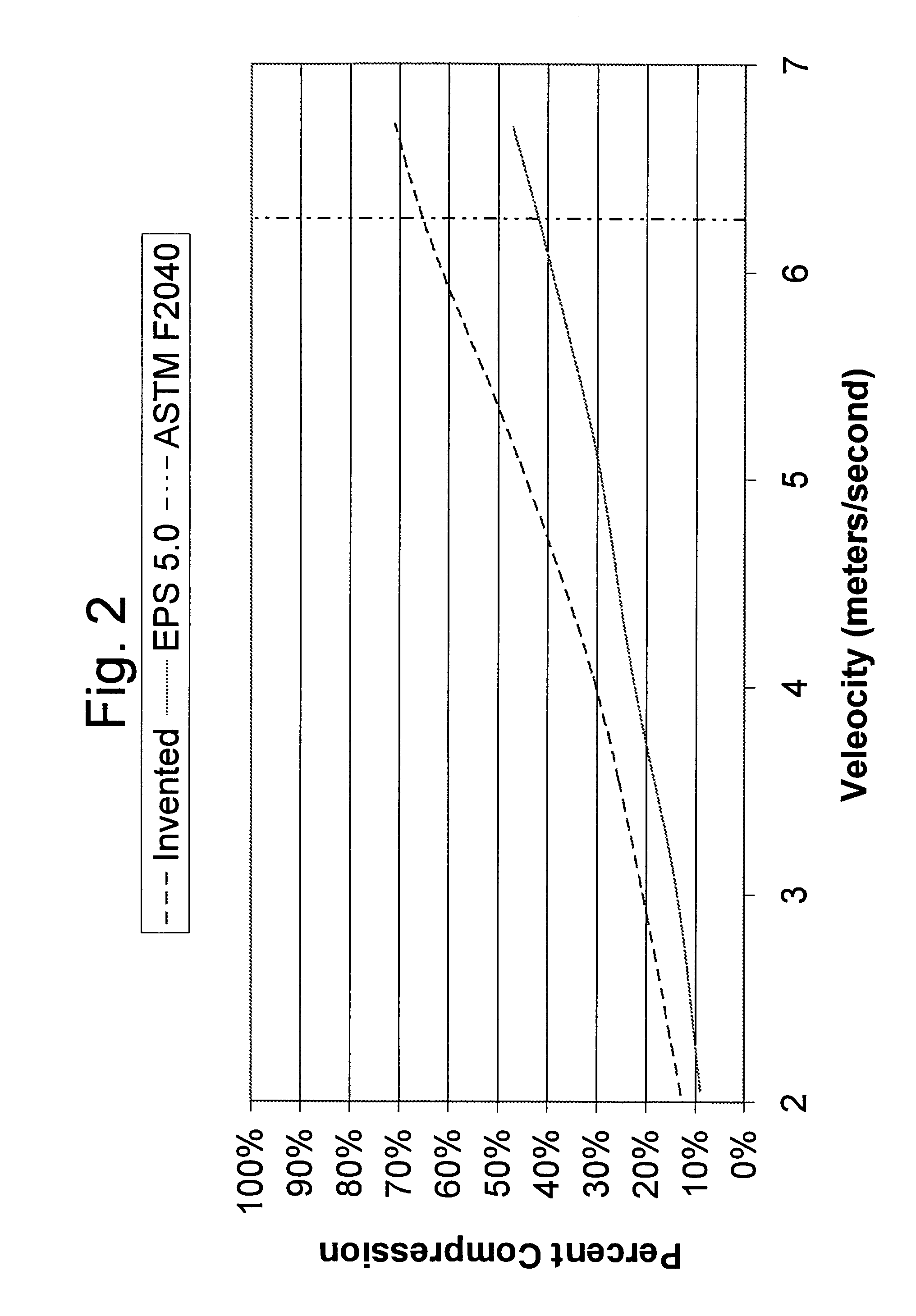
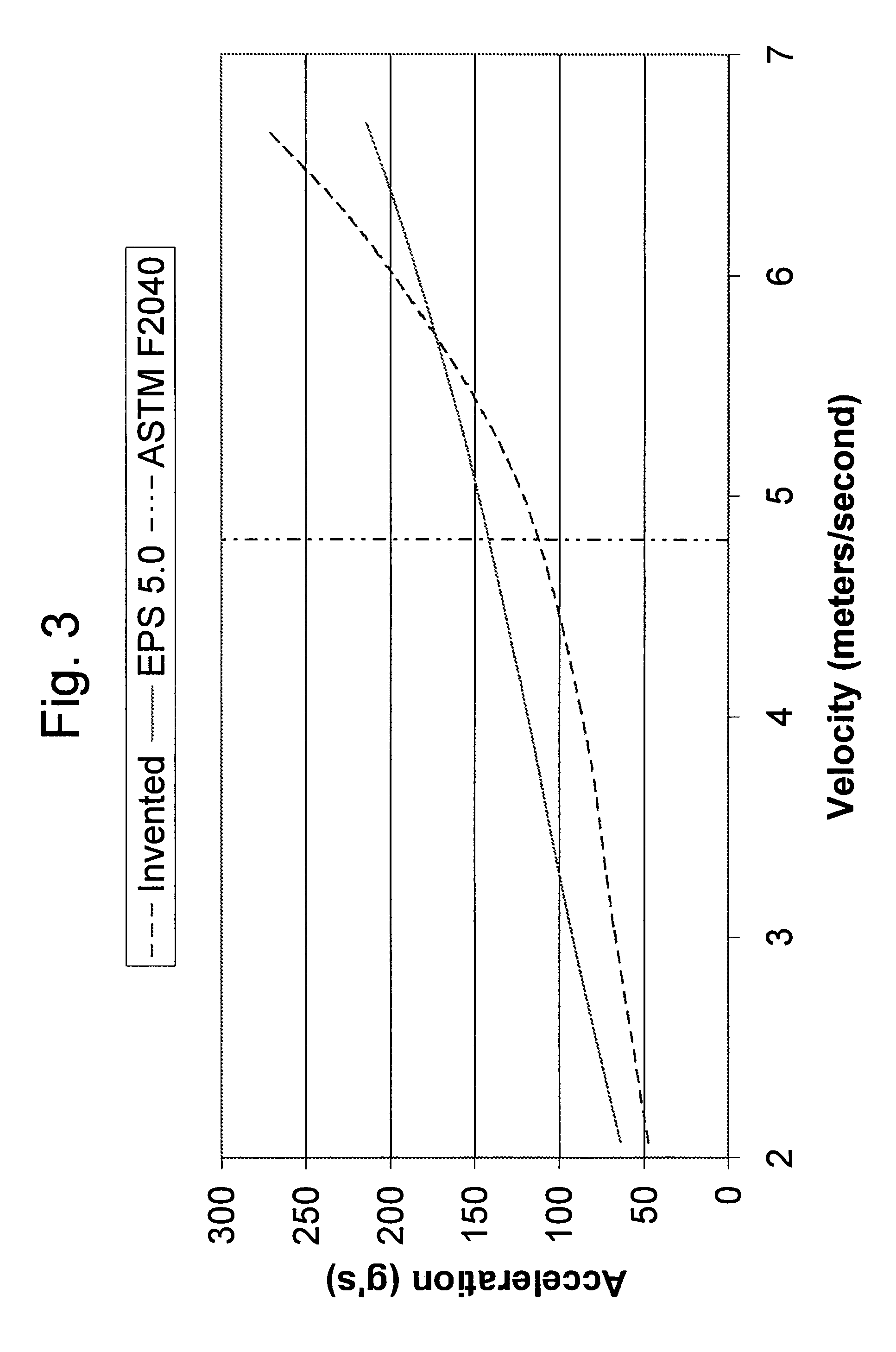
[0066]In another experiment, a foam according to the invention was compared to EPS to test break-through acceleration and percent compression versus impact velocity according to ASTM F2040. In this experiment, the Foam No. 2 from Table 2 was used and compared to EPS. The test samples for each of the invented and EPS foams were square samples measuring 5.5″×5.5″×1″ thick. The tests were conducted first using a flat circular impactor having a 4-inch diameter, and then using a spherical impactor that also had a 4-inch diameter. The results are provided in FIGS. 1–2 and 3–4 for the flat and spherical impactors respectively. As can be seen from FIG. 1, using the flat impactor the invented foam exhibited significantly less breakthrough acceleration than EPS for impact velocities from 2 to about 6.5 m / s (i.e. resulting from unabsorbed energy which was transmitted through the foam); the invented foam exhibited about 50% less breakthrough acceleration measured in g's from 2 to about 6 m / s. A...


PUM

PropertyMeasurementUnit
weight percentaaaaaaaaaa
impact speedsaaaaaaaaaa

Abstract

A viscoelastic foam is provided having an amine-based polyol system to impart strength, recoverability and endurance to the foam, and an appropriately selected trifunctional non-amine-based polyol system to provide flexibility to the foam. The combination of amine-based and non amine-based polyols provides a viscoelastic semi-rigid foam with excellent impact and recovery properties, recovering to substantially 100% of its initial volume and shape following an impact, yet with high rigidity and stiffness so that it is effective at absorbing high as well as low-energy impacts. A method of making the above viscoelastic foam is also provided. In a preferred embodiment, the foam is made using an allophanate-modified MDI prepolymer in order to provide the isocyanate in liquid form at standard temperature and pressure in order to simplify the production of the invented viscoelastic foams.

Description

BACKGROUND OF THE INVENTION[0001]Polymeric protective foams (e.g. protective foam layers) are widely used for impact force attenuation in a variety of safety-related applications. These include but are not limited to automotive applications, sport applications, bedding applications, footwear applications, and etc. In general, a protective foam layer is placed adjacent or against a part of a person's body in order to protect that body part (e.g. a head) during an impact with, for example, the ground or even another person's head.[0002]Protective foams function by absorbing and / or dissipating the impact energy from the force of an impact. An energy absorbing foam deforms or crushes upon impact thereby consuming a portion of the impact energy so that portion does not reach the underlying body part. An energy dissipating foam also spreads the impact force over a larger surface area than the actual area of impact so that the force per unit area is decreased for the underlying body part c...

Claims


Application Information

Patent Timeline
Patent Type & Authority Patents(United States)
IPC IPC(8): C08G18/28C08G18/10C08G18/40C08G18/50C08G18/78C08J9/00
CPCC08G18/10C08G18/4072C08G18/5021C08G18/7837C08G18/40C08G2101/0016C08G2105/02C08G2101/0058C08G2101/0083C08G2110/0016C08G2110/0058C08G2115/02C08G2110/0083
Inventor MILLIREN, CHARLES M.
Owner TEAM WENDY
Why Eureka
Try Eureka