
Matrix driven liquid crystal display module system, apparatus and method

a liquid crystal display module and matrix technology, applied in the field of color display methods, can solve the problems of time lag or delay between two periods, flickering sensation of pictures, clumsy movement of pictures, etc., and achieve the effect of reducing the number of channels, reducing the display frequency and power consumption of display devices, and reducing the request for the time response speed of display devices

Inactive Publication Date: 2006-07-18
AU OPTRONICS CORP
View PDF8 Cites 9 Cited by
  • Summary
  • Abstract
  • Description
  • Claims
  • Application Information

AI Technical Summary

Benefits of technology

[0035]Also provided is a personal computer (PC) system which includes a video sub-system that can reduce the number of channels at an interface by employing an output channel.
[0036]According to the present invention, the display frequency and the power consumption of the display device can be reduced without deteriorating the display quality. Further, requests for the time response speed of the display device can be reduced.

Problems solved by technology

When the length of this rewriting time is greater than the response time of the human eye, a person viewing motion pictures experiences a flickering sensation and the movement in the pictures seems clumsy.
In addition, since the display is provided in response to the data writing, a time lag or delay occurs between the two periods.
Since some driving power is consumed each time a display is repeated, power is wasted.
However, since the color TV standard method was standardized, as an NTSC method that is compatible with the monochrome method, development of the color field sequential method was halted.
If such a condition exists, it would be not economical for a flickering frequency that is higher than necessary to be provided for a color that a person does not perceive very well.
In addition, a person will visually feel uncomfortable if a satisfactory refresh frequency is not provided for a color that the person perceives well.

Method used


Image

  • Matrix driven liquid crystal display module system, apparatus and method
  • Matrix driven liquid crystal display module system, apparatus and method
  • Matrix driven liquid crystal display module system, apparatus and method

Examples


example writing form

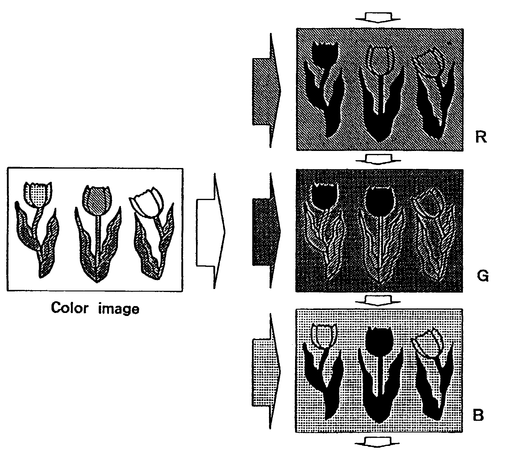
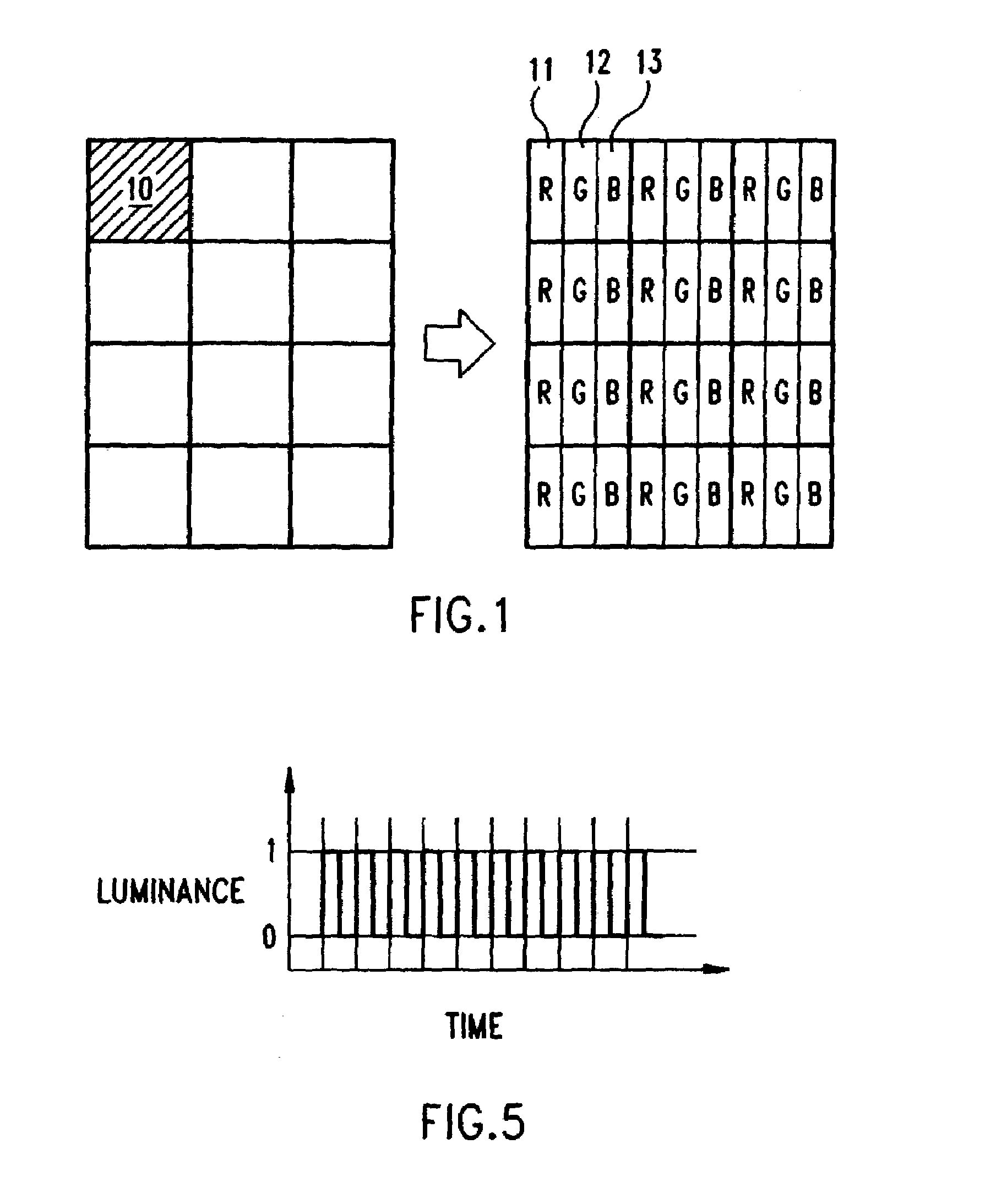
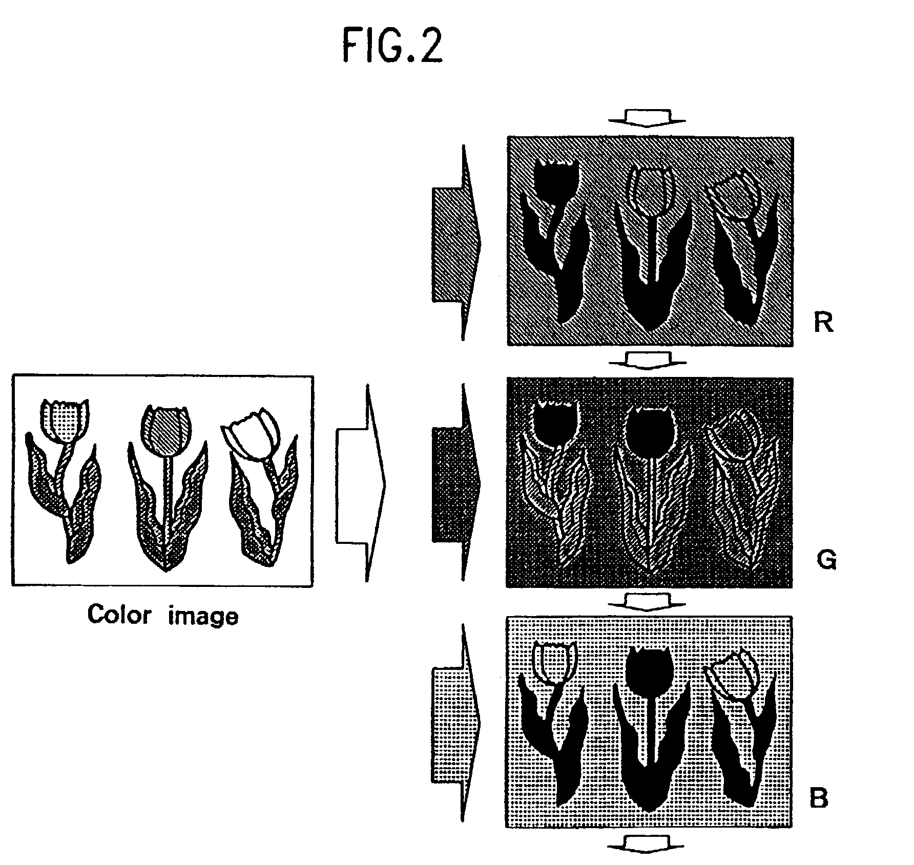
[0091]In FIG. 12 is shown example data writing based on H line inversion (inversion for each H line). In FIG. 12, +G, −G, +B, −B, +R and −R denote the positive (+) and the negative (−) writing of green / blue / red data, and squares correspond to sub-pixels. Blank squares represent sub-pixels for which data are not written. While taking into account the technical idea of the present invention and the most efficient writing method based on H inversion, the AC driving is completed after four frames. The “frame” in this example does not always correspond to the definition employed for FIGS. 2 and 6.

[0092]This is only an example writing form, and it would be obvious for one having ordinary skill in the art that the technical idea of the present invention can be employed for V inversion (line inversion), dot inversion or frame inversion.

Signals for Individual Sections

[0093]In FIG. 13 are shown signals output by the video controller 120. Vsync denotes a vertical synchronous control signal; Hs...


PUM

PropertyMeasurementUnit
FWHMaaaaaaaaaa
display timeaaaaaaaaaa
frequencyaaaaaaaaaa

Abstract

Provided are a color display driving principle obtained while taking into account a difference in eye sensitivity to the flickering of differently colored lights, a TFT liquid crystal display module structure that is adequate for this method, and a double-panel projection type display device.The count of the G (green) color data that can be written is increased compared with the count for the other primary colors, or the display period for green can be extended. The repetitive unit is set to R, G, B and G, so that a satisfactory refresh rate can be set for the important color G. Therefore, the overall refresh frequency and the power consumed by the display device can be reduced without deterioration of the display quality, and requests for the time response speeds by the display device can be reduced.

Description

[0001]This is a division of application Ser. No. 09 / 312,004, filed May 14, 1999, now U.S. Pat. No. 6,556,181.FIELD OF THE INVENTION[0002]This invention relates to a general color display method, and more specifically to a color display method which takes into account a difference in the sensitivities of users relative to a flicker frequency.BACKGROUND OF THE INVENTION[0003]An additive color mixture method is employed as a general coloring method. According to this method, when light beams of two or more colors impinge on the retina, they are mixed and are perceived as another color. This method serves as the basic principle for current color display devices. R (red), G (green) and B (blue) are employed as three discrete color beams (beams of primary colors that cannot be produced by mixing another two colors). Another method that is used is a subtractive color mixture method for which are employed three complementary color beams, C (cyan), M (magenta) and Y (yellow) that respectivel...

Claims


Application Information

Patent Timeline
Patent Type & Authority Patents(United States)
IPC IPC(8): G09G5/10G02F1/133G09G3/20G09G3/34G09G3/36H04N5/74H04N9/31
CPCG09G3/3413G09G3/3607G09G3/3659H04N9/3197H04N9/3111H04N9/312H04N9/3155H04N9/3164G09G3/3677G09G2300/0814G09G2310/0235
Inventor YAMADA, FUMIAKISAKAGUCHI, YOSHITAMI
Owner AU OPTRONICS CORP
Learn More