Optical assembly to be mounted on a microscope for measuring periodic movements of a microstructure

a technology of optical assembly and microscope, which is applied in the direction of optics, microscopes, devices using optical means, etc., can solve the problem of generally much faster movement of components, and achieve the effect of maximum light efficiency

Active Publication Date: 2006-07-18
POLYTEC
View PDF8 Cites 4 Cited by
  • Summary
  • Abstract
  • Description
  • Claims
  • Application Information

AI Technical Summary

Benefits of technology

[0010]At the same time, and this produces the great advantage of the invention relative to previous, typically specially configured microscopes, the optical assembly according to the invention includes in its beam path between the two field lenses a beam splitter for coupling light pulses of a stroboscope lamp. Based on the invention, it is also possible for the first time to perform stroboscopic measurements for detecting microstructure movements with a commercially available, standardized microscope without special modifications to this microscope. This is because in all cases, such microscopes are provided with a standardized C-mount for mounting a camera. The adapter according to the invention thus shifts the interface for attaching an electronic camera upwards and enables light pulses of a stroboscopic lamp to be coupled in the stretch of the beam path obtained in this way without requiring any modifications to the microscope itself. Nevertheless, the full functionality of the microscope is given, because a (standardized) camera mount is also provided after the mounting of the optical assembly according to the invention and can be used both for an electronic camera and also for a scanning vibrometer or the like.
[0011]Special advantages result when the field lenses and the imaging lens system are dimensioned and arranged so that the individual rays of the beam from each image point of the first object image emerge from the second object image imaged above the upper field lens at the same angles as from the first object image. This enables a cascade arrangement for the system and two or even more optical assemblies according to the invention can be connected one after the other. However, even without this cascade arrangement, such a refinement of the invention is advantageous because all other devices, which likewise couple light into the beam path, can be used with the same alignments as if they were mounted directly on the microscope.
[0012]Preferably, the beam splitter provided in the optical assembly according to the invention is dimensioned and arranged so that the light pulses of the stroboscope lamp are coupled into the incident beam path of the microscope according to the rules of Köhler illumination. According to these rules of illumination, the individual beams diverging from one point of the light source are always incident on the object plane in parallel, so that a very uniform illumination of the object field itself is produced if the light source emits non-uniformly in the plane.
[0013]Preferably, the stroboscope lamp itself is part of the optical assembly. This then produces a fixed spatial arrangement of the stroboscope lamp relative to the beam splitter. Thus there is no need for any alignment for coupling the stroboscope light via the beam splitter into the incident beam path of the microscope.
[0014]The stroboscope lamp is preferably an LED with an aperture angle θ and with a phosphor surface of a diameter d. The aperture angle and the diameter of the phosphor surface satisfy the relationship: d*θ<0.5, where d is in mm and θ is in rad. More preferably, the LED has an optical output of more than 10 mW. These initial conditions have proven to be optimal in achieving the results according to the invention.
[0015]The imaging lens system is preferably a combination system, which guarantees aberration-free imaging. Such lens systems are known.

Problems solved by technology

However, the special problem for microstructures is that the movements of the components are generally much quicker (at frequencies up to 100 MHz) than the smallest time window needed by the camera in order to be able to record an image.

Method used


Image

  • Optical assembly to be mounted on a microscope for measuring periodic movements of a microstructure
  • Optical assembly to be mounted on a microscope for measuring periodic movements of a microstructure
  • Optical assembly to be mounted on a microscope for measuring periodic movements of a microstructure

Examples


Embodiment Construction

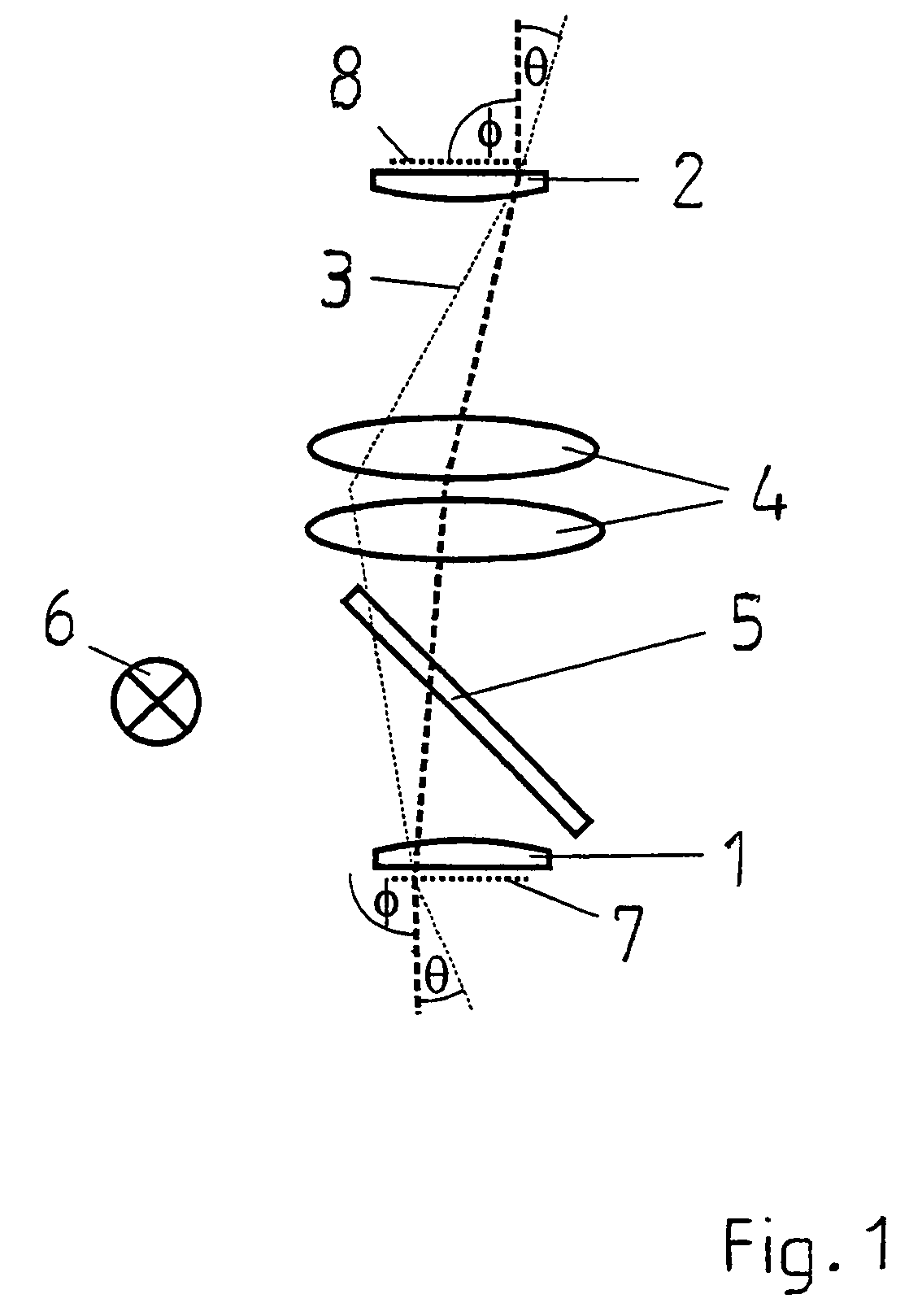
[0023]FIG. 1 shows the principle configuration of an optical assembly according to the invention, including a lower field lens 1, an upper field lens 2, an imaging lens system 4 in the beam path 3 of these lenses, and a beam splitter 5 for coupling the light pulses of a stroboscope lamp 6 into the microscope beam path. As shown by FIG. 1, a first object image 7 is imaged above the upper field lens 2 on a second object image 8 by the optical assembly according to the invention. The exceptional feature of the embodiment described here is that the individual rays of the beam from each image point of the first object image 7 emerge from the second object image 8 at the same angles θ, φ as from the first object image 7 itself. According to this embodiment, the imaging lens system 4 is an aberration-corrected lens system for 1:1 imaging.

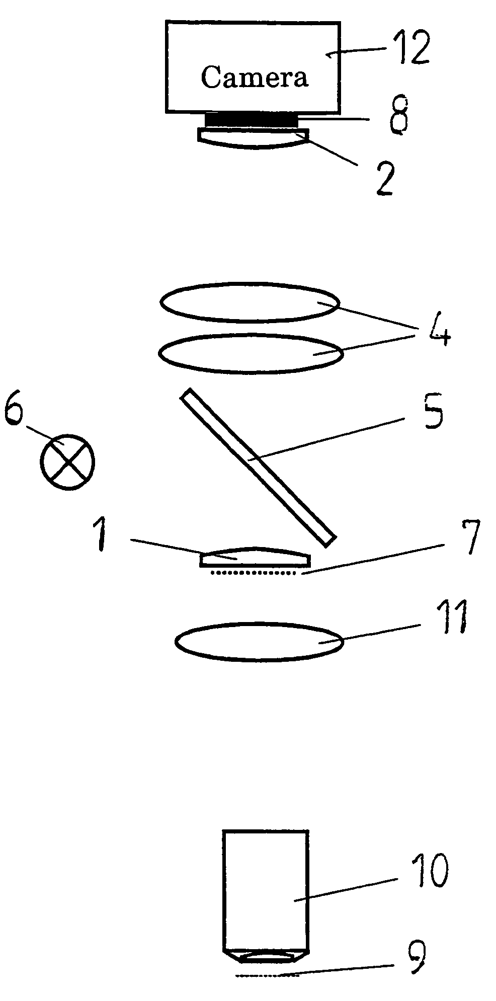
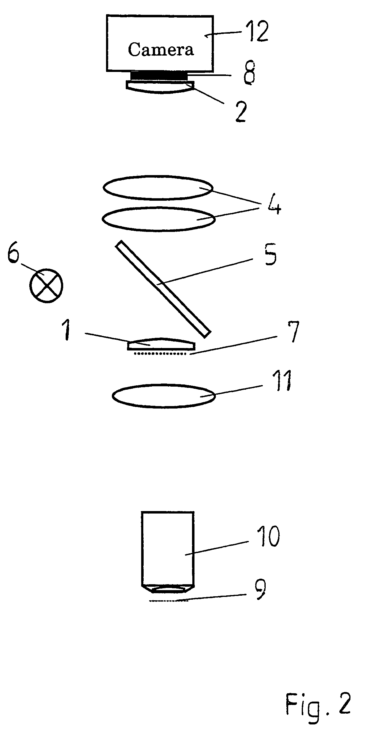
[0024]In a similar schematic representation, FIG. 2 shows how the optical assembly according to the invention interacts with the other components of the m...


PUM


Abstract

An optical assembly to be mounted on a microscope for measuring micro-structures is provided, which images a first object image (7) onto a second object image (8) lying above the optical assembly and in this way shifts the object image at a standardized interface for a camera (12), as well as the interface for the camera itself, upwards. The optical assembly permits a stroboscope lamp (6) to be coupled into the incident beam path of the microscope over a beam splitter (5) without requiring any structural modifications to the microscope. Instead, the optical assembly according to the invention is simply mounted on the C-mount of the microscope. The invention enables the use of stroboscope lamps in commercially available microscopes, which otherwise are not suitable for stroboscopic examinations.

Description

[0001]The invention relates to an optical assembly to be mounted on a microscope for measuring periodic movements of a microstructure.[0002]In particular, miniaturized components in microsystem technology require special measurement systems if the movements and degrees of freedom of the individual elements of the microsystem are to be examined and measured. For the most part, a microscope and an electronic camera are indispensable for this purpose.[0003]For component movements and degrees of freedom perpendicular to the object plane of the microscope, the interferometric measurement method using a scanning vibrometer has proven to be advantageous. Corresponding to the wave-lengths of the light used in this method, very small movements of the miniaturized components can be measured.[0004]Movements of the components in the object plane of the microscope, such as the rotation of a micro-gear, require a different measurement method. For this purpose, typically a microscope with a mounte...

Claims


Application Information

Patent Timeline
Patent Type & Authority Patents(United States)
IPC IPC(8): G01P3/40G02B21/00G02B21/06G02B21/36
CPCG02B21/0016G02B21/361G02B21/06
Inventor REMBE, CHRISTIANDRABENSTEDT, ALEXANDER
Owner POLYTEC
Why Eureka
Try Eureka