Fluidic cooling systems and methods for electronic components

a technology of electronic components and fluid cooling, applied in the field of electronic components, can solve the problems of increasing the difficulty of providing adequate cooling, reducing the service life of electronic components, so as to achieve a reliable sealing structure

Active Publication Date: 2006-07-18
GLOBALFOUNDRIES U S INC
View PDF18 Cites 44 Cited by
  • Summary
  • Abstract
  • Description
  • Claims
  • Application Information

AI Technical Summary

Benefits of technology

[0012]It is another object of the present disclosure to provide a reliable sealing structure for an electronic component to allow cooling fluid to be sprayed directly over the components back surface, yet provide a barrier so as to not let the cooling fluid contact the connections on the front surface of the component.
[0013]It is yet another object of the present disclosure to provide a fluid isolation system for electronic components. The isolation module affords long term environmental protection from direct spraying of a cooling fluid on a portion of the electronic component.

Problems solved by technology

The heat generated by components having a large power density level can be destructive or damaging to the electronic component and / or to other parts of the electronic device.
The electronic components in these devices are therefore being made smaller and more powerful, which can increase the difficulty of providing adequate cooling.
However, it is becoming increasingly difficult to cool high-power density components with prior conduction and convection thermal management cooling techniques.
Unfortunately, this thermal interface material and the heat sink can increase the thermal resistance of the electronic component.
Accordingly, these prior systems have not proven effective for cooling smaller, more powerful electronic components.
Unfortunately, the specialized cooling fluid and design requirements necessary for such systems have proven difficult to achieve and proven not economically viable for smaller consumer devices.

Method used


Image

  • Fluidic cooling systems and methods for electronic components
  • Fluidic cooling systems and methods for electronic components
  • Fluidic cooling systems and methods for electronic components

Examples


Embodiment Construction

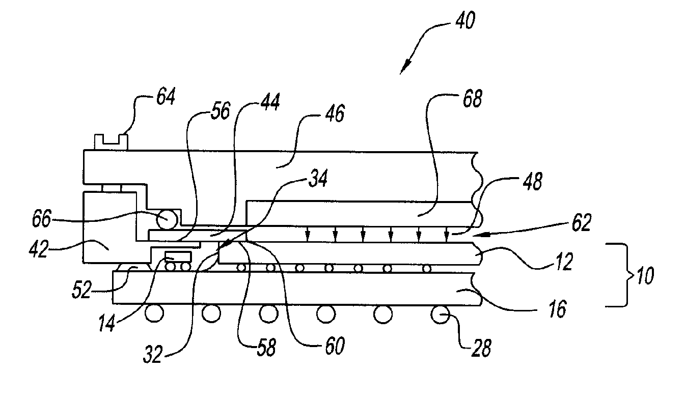
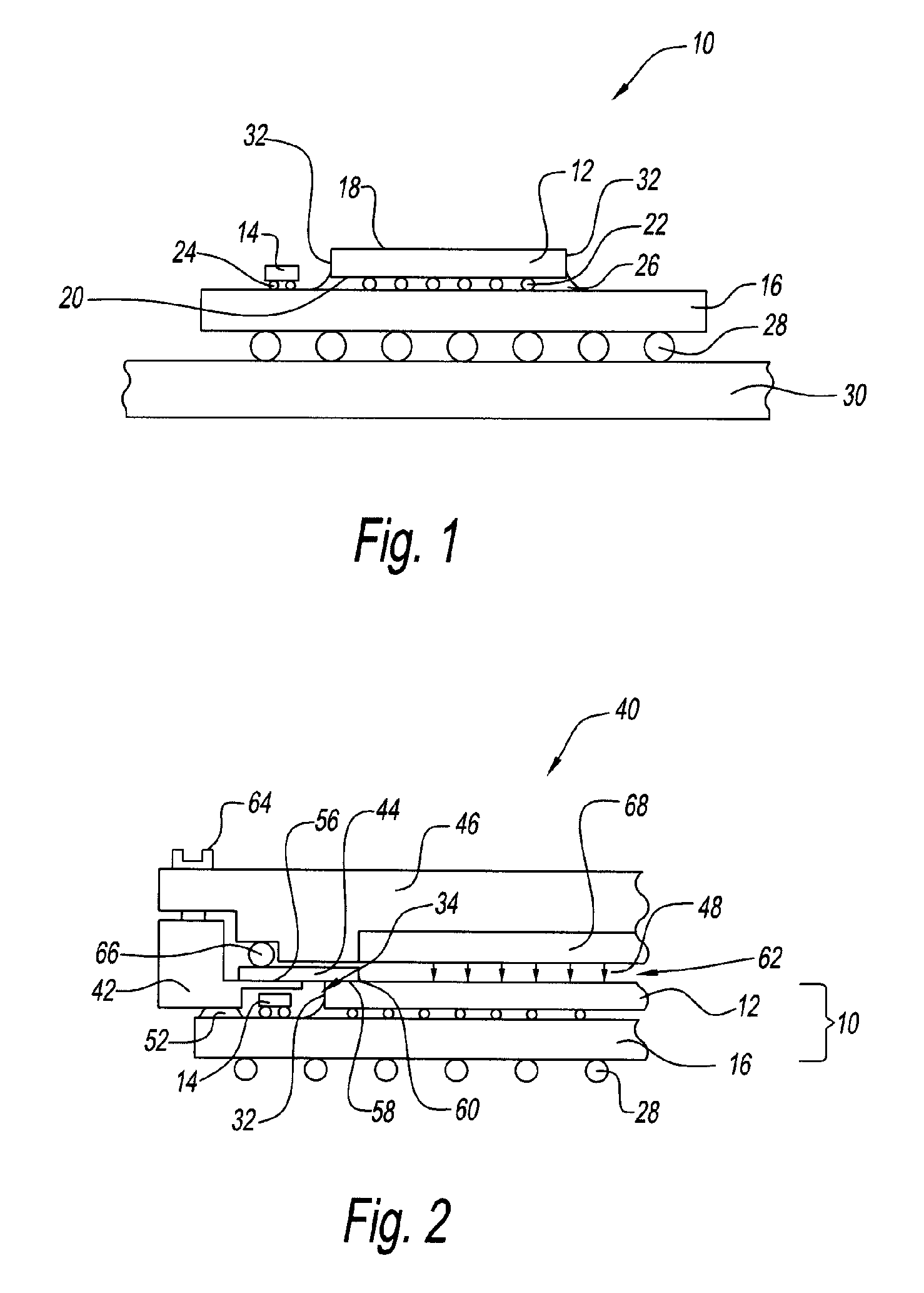
[0023]Referring to the drawings and in particular to FIG. 1, an exemplary embodiment of relevant portions of an electronic component is illustrated by way of reference numeral 10. Electronic component 10 is illustrated by way of example as a single chip module (SCM) package having one or more discrete devices, such as, but not limited to, an integrated circuit chip, a capacitor, a resistor, a memory device, and similar discrete electronic devices.

[0024]In FIG. 1, electronic component 10 is illustrated having one integrated circuit chip 12 and one capacitor 14 secured to a chip carrier 16. Chip 12 has a high power density level, namely generates a large amount of heat from a small surface area. In one exemplary embodiment, chip 12 has a power density level of at least about 2 to about 4 watts per square millimeter (W / mm2).

[0025]Chip 12 has a front surface 18 and a back surface 20. Front surface 18 is secured to carrier 16 by one or more solder connections 22 so that the chip and carr...


PUM


Abstract

A cooling system for an electronic component on a component carrier is provided. The system includes a frame, a spray manifold, and a sealing member. The frame has an opening and is connectable to the component carrier so that an annular area is defined between the opening and the electronic component. The spray manifold is sealed over the opening to define a spray area over a back surface of the electronic component. The spray manifold sprays a cooling fluid on the back surface. The sealing member seals the annular region so that input / output connectors on the component carrier are isolated from the cooling fluid.

Description

BACKGROUND OF INVENTION[0001]1. Field of the Invention[0002]The present disclosure relates to electronic components. More particularly, the present disclosure relates to electronic components having fluidic cooling systems and methods.[0003]2. Description of Related Art[0004]Electronic devices, such as computers, cell phones, network servers, and others, include a number or plurality of electronic components. Many of these electronic components, such as integrated circuit chips, resistors, capacitors, and others, generate heat during use.[0005]The amount of heat generated is typically proportional to the speed or power of the electronic component. The heat generated by components having a large power density level can be destructive or damaging to the electronic component and / or to other parts of the electronic device. Thus, the removal and / or dissipation (hereinafter “removal”) of this heat is often desired.[0006]The consumer acceptance of many electronic devices is affected by the...

Claims


Application Information

Patent Timeline
Patent Type & Authority Patents(United States)
IPC IPC(8): H05K7/20
CPCH01L23/4735H01L2224/32225H01L2224/16H01L2924/15311H01L2224/73204H01L2924/00014H01L2924/00011H01L2224/0401
Inventor COLGAN, EVAN G.POMPEO, FRANK L.DAVES, GLENN G.TOY, HILTON T.FURMAN, BRUCE K.EDWARDS, DAVID L.GAYNES, MICHAEL A.FAROOQ, MUKTA G.KANG, SUNG K.OSTRANDER, STEVEN P.WILLIAMSON, JAIMAL M.SHIH, DA-YUANHENDERSON, DONALD W.
Owner GLOBALFOUNDRIES U S INC
Why Eureka
Try Eureka