
Color interpolation for image sensors using a local linear regression method

a color interpolation and image sensor technology, applied in the field of image processing, can solve the problems of color aliasing artifact generation, poor correlation among neighboring pixels, and higher noise amplification during color correction processing, so as to reduce noise amplification, less chromatic aliasing, and less blurring

Inactive Publication Date: 2006-07-18
AGILENT TECH INC
View PDF9 Cites 25 Cited by
  • Summary
  • Abstract
  • Description
  • Claims
  • Application Information

AI Technical Summary

Benefits of technology

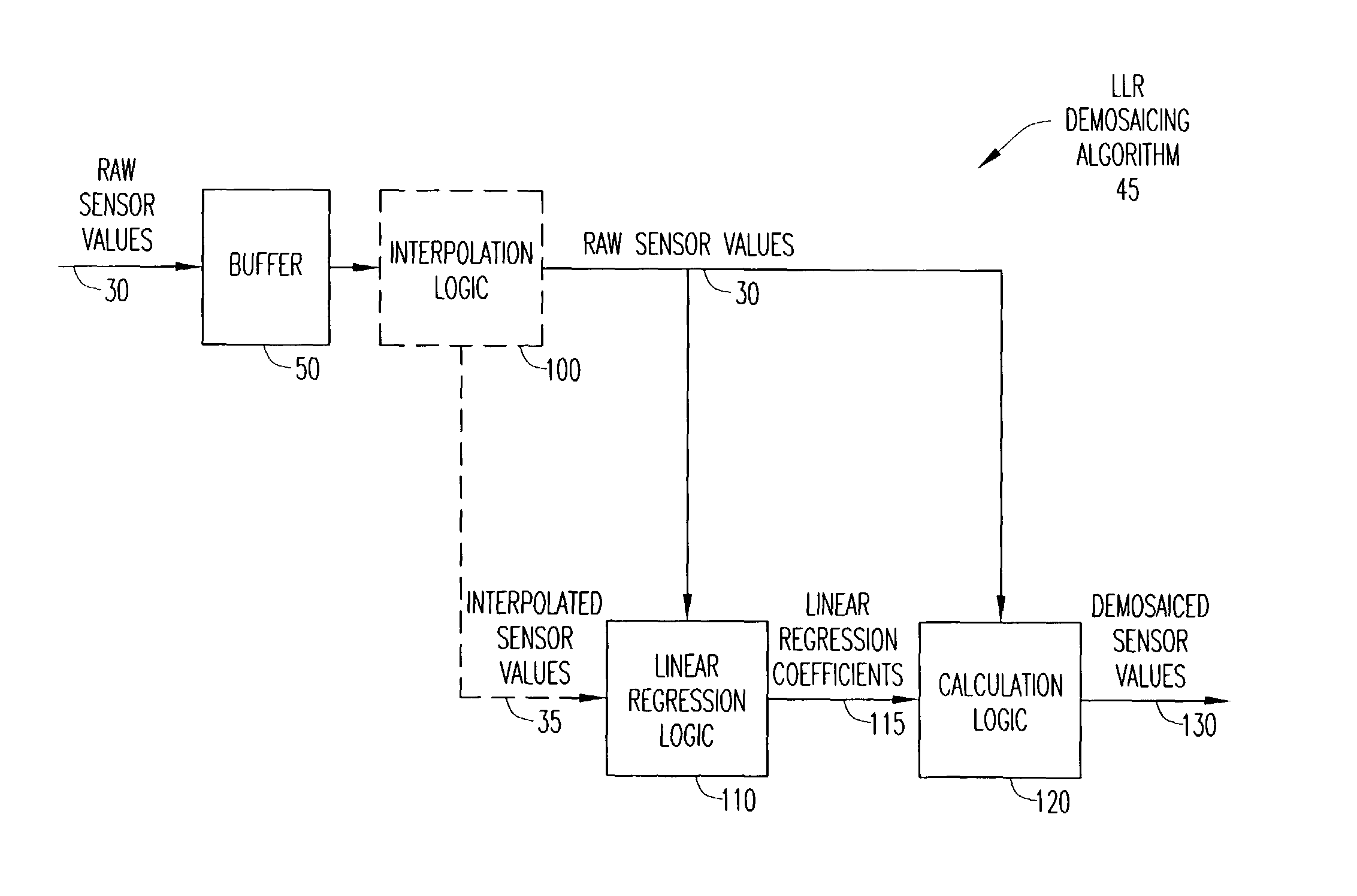
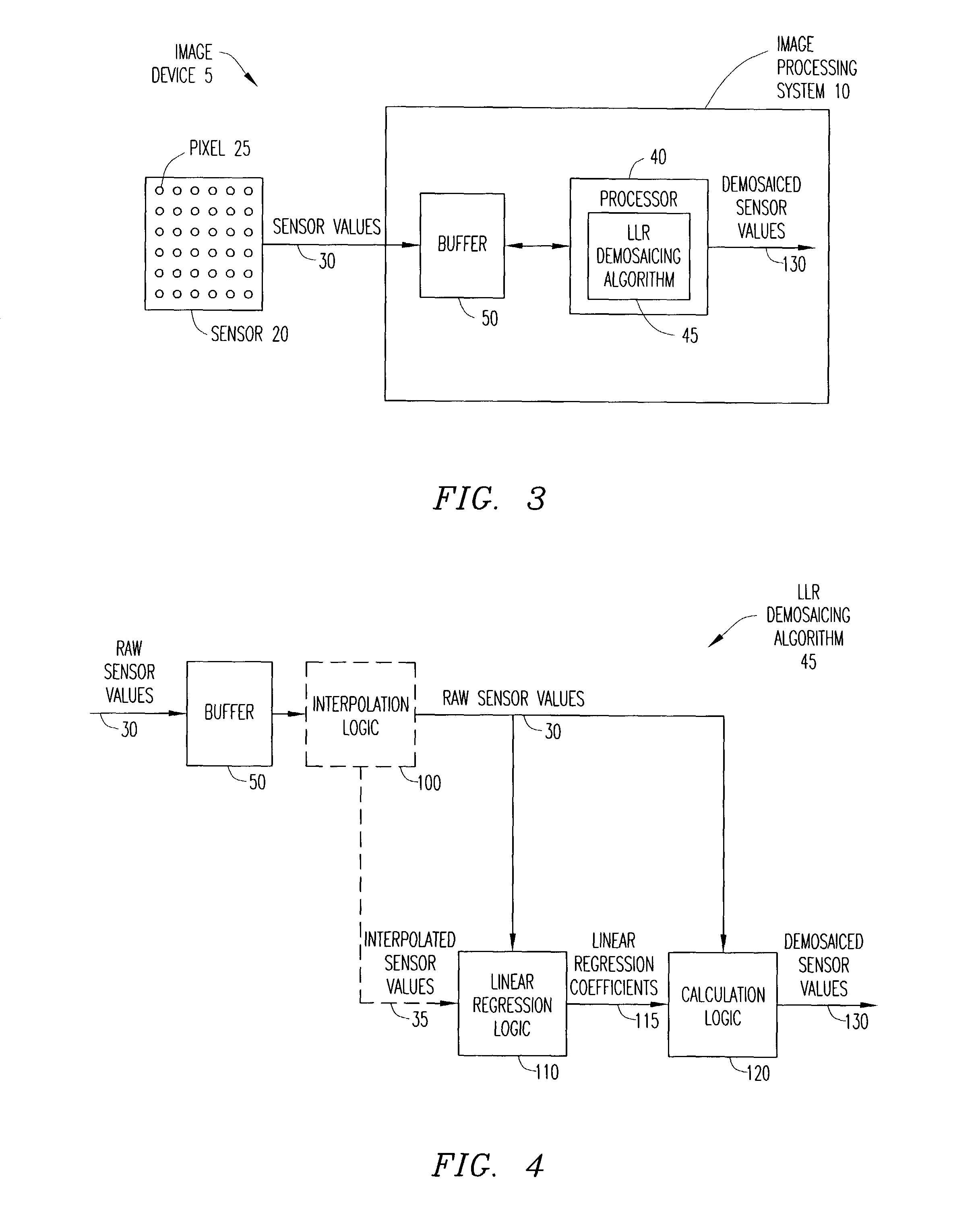
[0013]Since all missing pixels of a color channel within one region are calculated with a single set of linear regression coefficients, the linear relations between sensor values of the pixels within the region are preserved, resulting in less blurring and less chromatic aliasing in the final image compared with neighboring correlation assumption demosaicing methods. In addition, the noise terms between different color channels are correlated, thereby reducing noise amplification in subsequent processing compared with other neighbor correlation and color correlation assumption demosaicing methods. Furthermore, the invention provides embodiments with other features and advantages in addition to or in lieu of those discussed above. Many of these features and advantages are apparent from the description below with reference to the following drawings.

Problems solved by technology

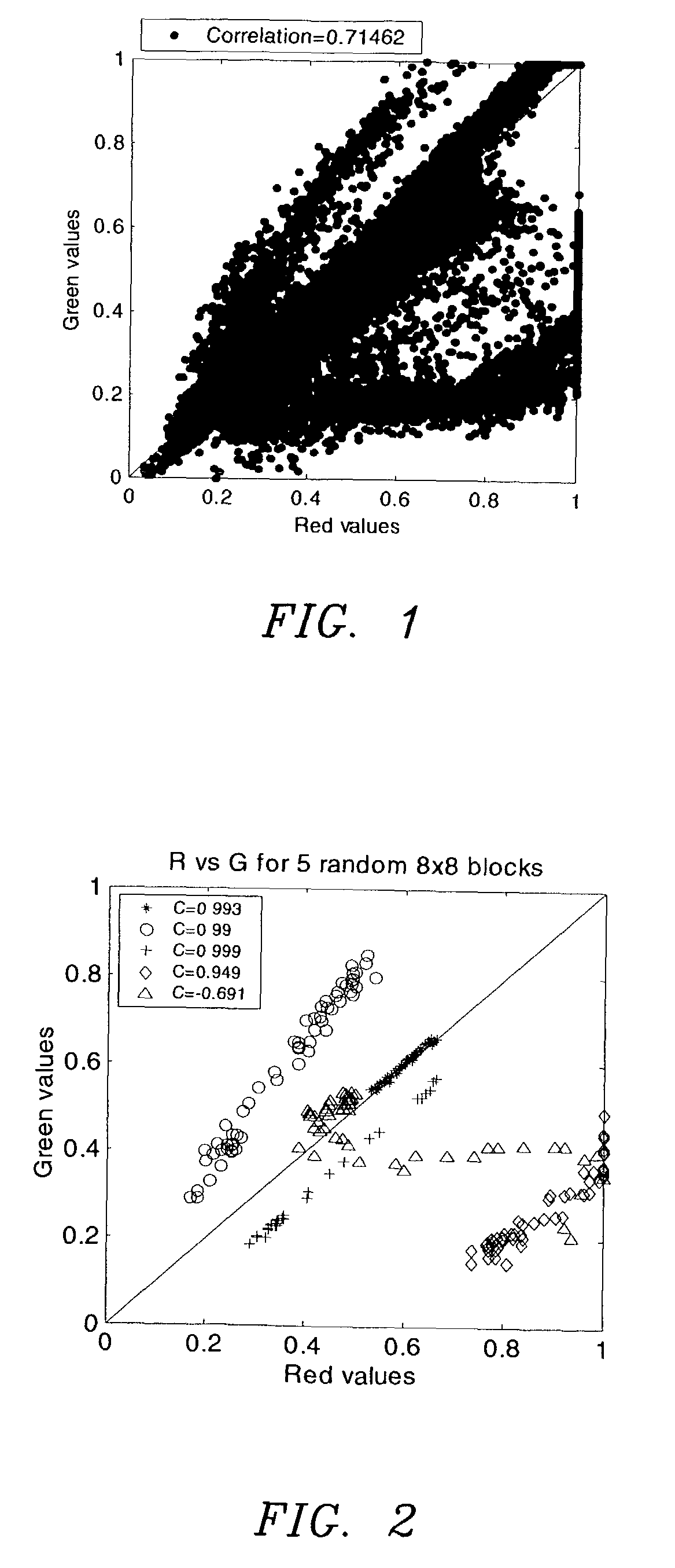
However, for image regions with sharp lines and edges, the correlation among neighboring pixels may be poor.
Therefore, demosaicing based on the neighboring correlation assumption may generate color aliasing artifacts along edges and in regions with fine details.
In addition, neighboring correlation assumption demosaicing methods may generate images with independent noise levels among the color planes, resulting in higher noise amplification during color correction processing.
However, in some images, the improved edge and line reconstruction comes at the cost of reduced color saturation due to assumptions of fixed positive correlation among different color planes.

Method used


Image

  • Color interpolation for image sensors using a local linear regression method
  • Color interpolation for image sensors using a local linear regression method
  • Color interpolation for image sensors using a local linear regression method

Examples


Embodiment Construction

[0027]The numerous innovative teachings of the present application will be described with particular reference to exemplary embodiments. However, it should be understood that these embodiments provide only a few examples of the many advantageous uses of the innovative teachings herein. In general, statements made in the specification do not necessarily delimit any of the various claimed inventions. Moreover, some statements may apply to some inventive features, but not to others.

[0028]For most image sensors, at any pixel location, the captured sensor values for different colors are highly correlated, meaning that the sensor values for different colors are predictably sloped and offset from one another. The correlation amongst the different colors is a result of the photo-detectors at a pixel location having largely overlapping sensitivities and the fact that objects captured in an image generally have smooth surface reflectance curves.

[0029]However, the correlation amongst colors te...


PUM


Abstract

An image processing system and demosaicing method are provided to calculate estimated missing color sensor values in an image using a linear prediction from the raw color sensor value at the current pixel location. The raw image is divided into regions of sensor values, and the linear relations between color planes for each region are determined by a regression method that calculates the degree to which different color planes co-vary within each region The missing color sensor values per region are calculated as a scaled and shifted version of the raw color sensor values using linear regression coefficients determined from the local linear regression process.

Description

BACKGROUND OF THE INVENTION[0001]1. Technical Field of the Invention[0002]The present invention relates generally to image sensors, and specifically to image processing of sensor values.[0003]2. Description of Related Art[0004]Electronic image sensors are predominately of two types: CCDs (Charge Coupled Devices) and CMOS-APS (Complimentary Metal Oxide Semiconductor-Active Pixel Sensors). Both types of sensors typically contain an array of photo-detectors, arranged in a pattern, that sample light and / or color within an image. Each photo-detector corresponds to a pixel of an image and measures the intensity of light of the pixel within one or more ranges of wavelengths.[0005]In addition, both types of sensors may include a color filter array (CFA), such as the CFA described in U.S. Pat. No. 3,971,065 to Bayer (hereinafter referred to as Bayer), which is hereby incorporated by reference. With the Bayer CFA, each pixel sees only one wavelength range, corresponding to the perceived color...

Claims


Application Information

Patent Timeline
Patent Type & Authority Patents(United States)
IPC IPC(8): G06K9/00G06K9/32G06K9/36H04N1/46G06T1/00H04N1/60H04N9/04H04N9/07
CPCH04N9/045H04N23/843H04N25/134
Inventor ZHANG, XUEMEIKAKARALA, RAMAKRISHNASACHS, TODD S.
Owner AGILENT TECH INC
Learn More