Method and system for mobile IP home agent redundancy by using home agent control nodes for managing multiple home agents

a technology of home agent and control node, applied in the field of computer network communication, can solve the problems of large number of failed calls, significant user dissatisfaction, etc., and achieve the effects of reducing failed calls, eliminating or significantly reducing uploads and/or downloads, and improving user dissatisfaction

Inactive Publication Date: 2006-07-18
UTSTARCOM INC
View PDF13 Cites 172 Cited by
  • Summary
  • Abstract
  • Description
  • Claims
  • Application Information

AI Technical Summary

Benefits of technology

[0015]The method and system may help reduce failed calls in Mobile IP systems by eliminating or significantly reducing uploads and / or downloads of large numbers of mobility binding records. The method and system may also improve user dissatisfaction and reduce network congestion in Mobile IP systems.

Problems solved by technology

However, there are several problems associated with managing mobility binding records for Mobile IP.
One problem is a Mobile IP home agent may fail.
This large time period can lead to a large number of failed calls due to timeouts and other problems and also cause significant user dissatisfaction.
Another problem is that uploading or downloading large numbers of mobility binding records to a standby home agent can also cause significant network congestion leading to additional failed calls for other active home agents, especially if multiple home agents fail at the same time.
Another problem is that in many Mobile IP systems, home agents are managed by home agent control nodes.
If a home agent control node is managing multiple home agents and the home agent control node fails, thousands or perhaps tens of thousands of calls may fail.
The upload or download to a standby home agent control node can also lead to a large number of failed calls, significant user dissatisfaction or significant network congestion.

Method used


Image

  • Method and system for mobile IP home agent redundancy by using home agent control nodes for managing multiple home agents
  • Method and system for mobile IP home agent redundancy by using home agent control nodes for managing multiple home agents
  • Method and system for mobile IP home agent redundancy by using home agent control nodes for managing multiple home agents

Examples


Embodiment Construction

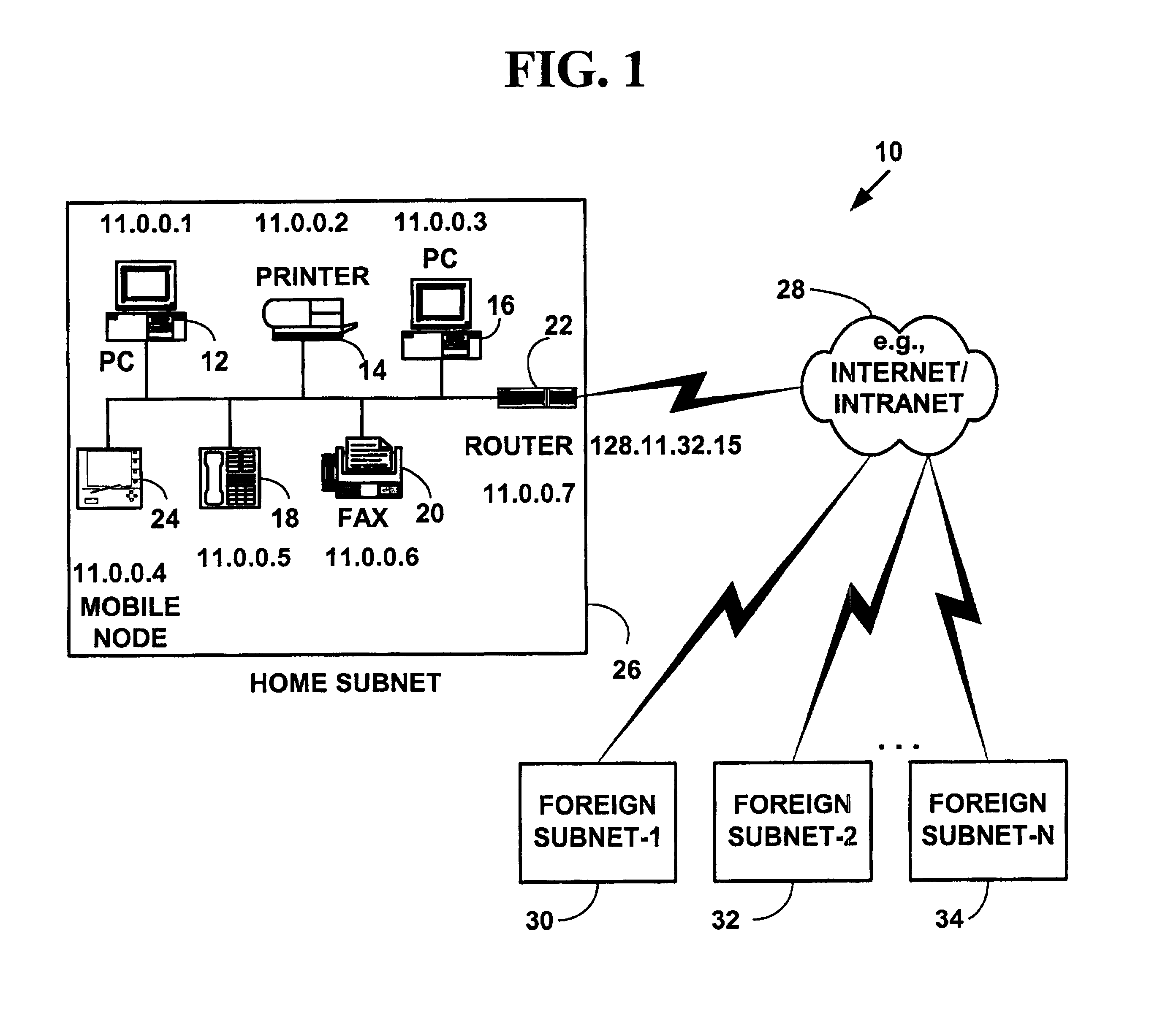
Exemplary Network System

[0030]FIG. 1 is a block diagram illustrating an exemplary network system 10 for preferred embodiments of the present invention. The network system 10 includes one or more local network devices 12, 14, 16, 18, 20, 22, 24, seven of which are illustrated. However, more or fewer local network devices can also be used. The local network devices are assigned network addresses (e.g., 11.0.0.x) on a local subnet 26 as is illustrated in FIG. 1. The local subnet 26 includes but is not limited to, a wireless netwbrk, a wired network, a wireless or wired LAN, an optical network or a cable network. However, other computer networks can also be used.

[0031]The local subnet 26 is connected to an external network 28 such as the Internet or an intranet via gateway router 22. As is known in the art, a gateway connects computer networks using different networking protocols or operating at different transmission capacities. As is known in the art, a router translates differences b...


PUM


Abstract

A method and system for Mobile Internet Protocol (IP) device redundancy. As mobile devices roam away from a home network and change a connective status, mobility binding records are sent to a multicast network address on the home network. The multicast network address multicasts the mobility binding records to other active Mobile IP home agent control nodes, standby home agent control nodes and standby home agents on the home network. The method and system allows standby home agent control nodes or standby home agents to be transparently switched for active home agent control nodes or active home agents that fail without downloading or uploading large numbers of mobility binding records after a failure. The method and system may also help reduce failed calls (e.g., data sessions including Voice over IP (VoIP), H.323, etc.), network congestion and improve user satisfaction in Mobile IP systems.

Description

FIELD OF INVENTION[0001]This invention relates to communications on computer networks. More specifically, it relates to a method and system for mobile internet Protocol home agent redundancy.BACKGROUND OF THE INVENTION[0002]The Internet Protocol (“IP”) is an addressing protocol designed to route traffic within a network or between networks. The Internet Protocol is used on many computer networks including the Internet, intranets and other networks. Internet Protocol addresses are typically assigned to “immobile” nodes on a network. An immobile node may be moved to a different computer network, but is typically associated with a static physical location (e.g., 3Com Corporation in Santa Clara, Calif.) and an immobile Internet protocol address.[0003]The Mobile Internet Protocol (hereinafter Mobile IP) allows “mobile” nodes to transparently move between different Internet Protocol sub-networks (“subnets”). Internet Protocol addresses are typically assigned to mobile nodes based on their...

Claims


Application Information

Patent Timeline
Patent Type & Authority Patents(United States)
IPC IPC(8): G06F15/16H04L12/28H04L12/56H04L69/40
CPCH04W8/12H04W4/16H04L69/40H04W80/04
Inventor BORELLA, MICHAEL S.SHARMA, ABHISHEKWARRIER, CHANDRABHATIA, RAVIDEEPALEX, ARUNKUNNATH, SUDHIR
Owner UTSTARCOM INC
Why Eureka
Try Eureka