
Loop control circuit and loop control method

a control circuit and loop technology, applied in the field of loop control circuit and loop control method, can solve the problems of reducing the efficiency of the overall program processing and increasing the overhead

Inactive Publication Date: 2006-07-18
LAPIS SEMICON CO LTD
View PDF6 Cites 2 Cited by
  • Summary
  • Abstract
  • Description
  • Claims
  • Application Information

AI Technical Summary

Benefits of technology

[0016]An object of the present invention is to provide an loop control circuit that executes control on a multiplexed loops with a minimum of overhead and loop control method adopted therein.

Problems solved by technology

For this reason, there is a problem in that the presence of an inner loop instruction is bound to increase the overhead to lower the efficiency with which the overall program is processed.

Method used


Image

  • Loop control circuit and loop control method
  • Loop control circuit and loop control method
  • Loop control circuit and loop control method

Examples


first embodiment

[0032](First Embodiment)

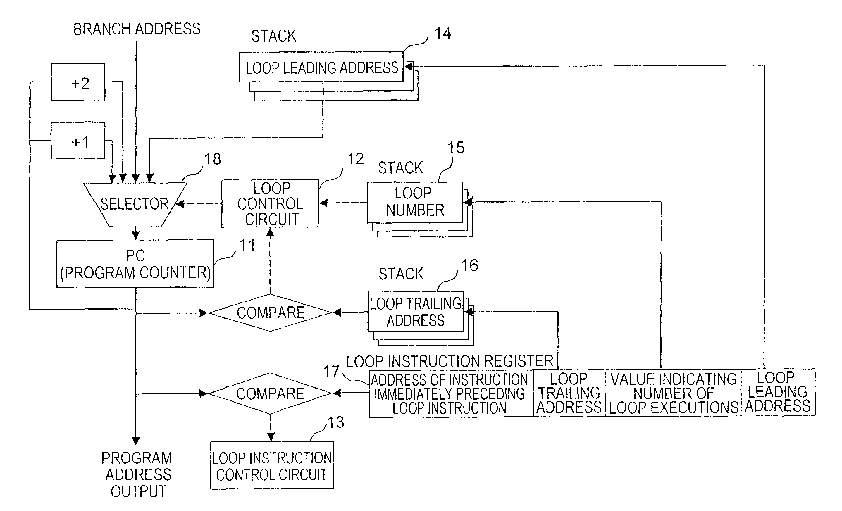
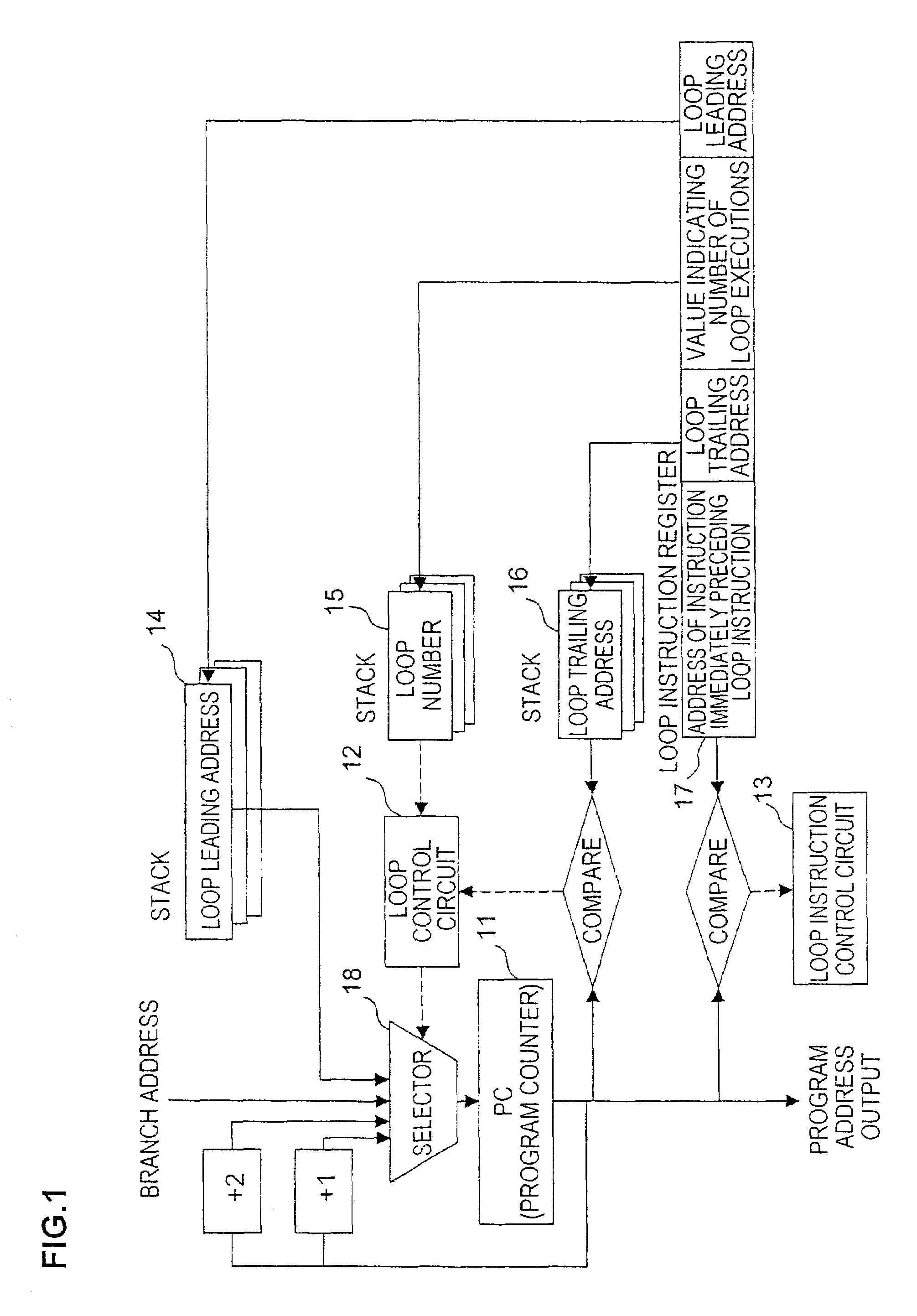
[0033]FIG. 1 is a block circuit diagram of the loop control circuit achieved in the first embodiment of the present invention. The loop control circuit in the first embodiment engages in operation as described below.

[0034]First, when executing a loop instruction, the “loop leading address” indicated in the loop instruction is pushed down into a “loop leading address” stack 14, the value indicating the number of loop executions is pushed down into a “loop number” stack 15 and the “loop trailing address” is pushed down into a “loop trailing address” stack 16.

[0035]Then, the “address of the instruction immediately preceding the loop instruction”, the loop leading address, the value indicating the number of loop executions and the loop trailing address are stored into their respective storage locations in a loop instruction register 17.

[0036]Next, a loop instruction control circuit 13 compares the address of the instruction immediately preceding the loop instruct...

second embodiment

[0055](Second Embodiment)

[0056]FIG. 4 is a block circuit diagram of the loop control circuit achieved in the second embodiment of the present invention. The loop control circuit in the second embodiment engages in operation as described below.

[0057]First, when executing a loop instruction, the “loop leading address” indicated in the loop instruction is pushed down into a “loop leading address” stack 24, the value indicating the number of loop executions is pushed down into a “loop number” stack 25 and the “loop trailing address” is pushed down into a “loop trailing address” stack 26.

[0058]Then, the “address of the instruction immediately preceding the loop instruction”, the value indicating the number of loop executions and the loop trailing address are stored into their respective storage locations in a loop instruction register 27.

[0059]Next, a loop instruction control circuit 23 compares the address of the instruction immediately preceding the loop instruction stored in the loop ...

third embodiment

[0068](Third Embodiment)

[0069]FIG. 5 is a block circuit diagram of the loop control circuit achieved in the third embodiment of the present invention. The loop control circuit in the third embodiment engages in operation as described below.

[0070]First, when executing a loop instruction, the “loop leading address” indicated in the loop instruction is pushed down into a “loop leading address” stack 34, the value indicating the number of loop executions is pushed down into the “loop number” stack 35 and the “loop trailing address” is pushed down into a “loop trailing address” stack 36.

[0071]Then, the “address of the instruction immediately preceding the loop instruction”, the loop leading address, the value indicating the number of loop executions and the loop trailing address are stored at their respective storage locations in either of two loop instruction registers 37a and 37b where data were input first.

[0072]Next, a loop instruction control circuit 33 compares the addresses of the...


PUM


Abstract

A loop control circuit and a loop control method that allow control on multiplexed loop operations to be executed with less overhead are provided. A loop control circuit comprises a means for address storage that stores in memory the address of a loop instruction at a second or subsequent stage in multiplexed loops or the address of the instruction immediately preceding the loop instruction when the loop instruction is executed for the first time, a means for loop instruction recurrence prediction that predicts a recurrence of the loop instruction at the second or subsequent stage by comparing the address of the loop instruction or the address of the instruction immediately preceding the loop instruction stored in memory with a value at a program counter and a means for loop instruction skipping that skips the loop instruction if it is predicted that the loop instruction is to occur next.

Description

BACKGROUND OF THE INVENTION[0001]1. Field of Invention[0002]The present invention relates to a loop control circuit and a loop control method and more specifically, it relates to a loop control circuit that executes control of multiplexed loops with a minimum of overhead and a loop control method adopted therein.[0003]2. Description of the Related Art[0004]In processors such as DSPs (digital signal processors), loop instructions are used to execute a specific processing repeatedly.[0005]The following is an explanation of a loop control method in the related art, given in reference to the drawings. FIG. 8 is a block circuit diagram that illustrates the operation of a loop control circuit in the related art. The number of stages in the stacks represents the number of multiplex loop levels in the hierarchy that can be achieved in this loop control apparatus. The circuit shown in FIG. 8 supports three loops. The term “stack” used in this context refers to an LIFO (last-in, first-out) me...

Claims


Application Information

Patent Timeline
Patent Type & Authority Patents(United States)
IPC IPC(8): G06F9/44G06F9/40G06F9/54G06F9/32G06F9/00G06F9/38
CPCG06F9/325
Inventor UEHARA, TERUAKI
Owner LAPIS SEMICON CO LTD
Learn More